System and methods for cooling electronic equipment
Active Publication Date: 2014-10-23
INERTECH IP
View PDF11 Cites 9 Cited by
Summary
Abstract
Description
Claims
Application Information
AI Technical Summary
This helps you quickly interpret patents by identifying the three key elements:
Problems solved by technology
Method used
Benefits of technology
Benefits of technology
The present patent disclosure describes systems and methods for cooling compressor motor inverters using a stable temperate pumped cooling fluid that is derived from an external source. This fluid can be used on multiple complementary systems that use a close tolerance pumped fluid for cooling. The use of this fluid allows for a safer operation, as it reduces the need for other protective sensors and parameters that are typically included on the systems. The systems and methods utilize a small portion of pumped refrigerant that is delivered to the motor inverter in close tolerances, which enables the compressor manufacturer to remove many of the limiting safety parameters that were included in the software and hardware of the system. The patent also describes a specific method for cooling the first fluid through a series of steps, including heat transfer, compression, and cooling using atmospheric air. The technical effects of the patent are improved safety and efficiency of cooling for data center IT cooling systems and reduced costs of the cooling system.
Problems solved by technology
Compressors using modern-day inverters (e.g., motor speed controllers or variable speed drives) require very tight temperature and humidity control.
Various manufacturers of compressors and chillers have experienced many problems with maintaining tight control of this cooling process because of the variables associated with the cooling media, as well as the environmental variables or conditions of the space in which the inverter operates.
These spaces are rarely cooled and the humidity within these spaces is rarely controlled.
The confluence of these two influences—media temperature and environmental conditions—presents certain challenges.
It is this tight control issue that has stymied many manufacturers and presented problems with safety and limit controls that need to be employed in order to protect the equipment during less than advantageous operating conditions.
The problem with these systems, however, is that they are inherently inefficient systems.
In addition, they limit and / or prevent operation of the motors at higher performance conditions if those conditions create a situation where the inverter could potentially be damaged or fail due to the influence of the outside variables.
This could create condensation, which could potentially damage the inverter or create a “short circuit” or grounding problem.
To avert these problems, chillers or compressors include dew point safety sensors that sense harmful levels of condensation and safety limit devices that reduce the amount of cooling water supplied to the inverter if the dew point safety sensors sense harmful levels of condensation.
As a result, the inverter would heat up and the inverter's heat sensors would cause the motor output to slow down or stop altogether.
These safety and limiting features protect the motor inverter, but they also limit the chiller output capacity at a critical point in the chiller efficiency operating curve.
This means that the compressor cannot continue to operate or operate at higher capacity at the most opportune operating condition for the chiller.
These safety and limiting features severely impede the compressor from operating over a greater span of water, refrigerant, and ambient temperatures.
The safety and limiting features also severely limit a chiller's ability to enter into and out of free cooling in a seamless manner.
This was mainly due to a concern for condensate and the resultant damage that could occur.
In some embodiments, mechanically cooling the second fluid includes mechanically cooling the second fluid to the extent that free cooling the first fluid is insufficient to cool the first fluid.
Method used
Image
Click on the blue label to locate the original text in one second.
Reading with bidirectional positioning of images and text.
Examples
Embodiment Construction
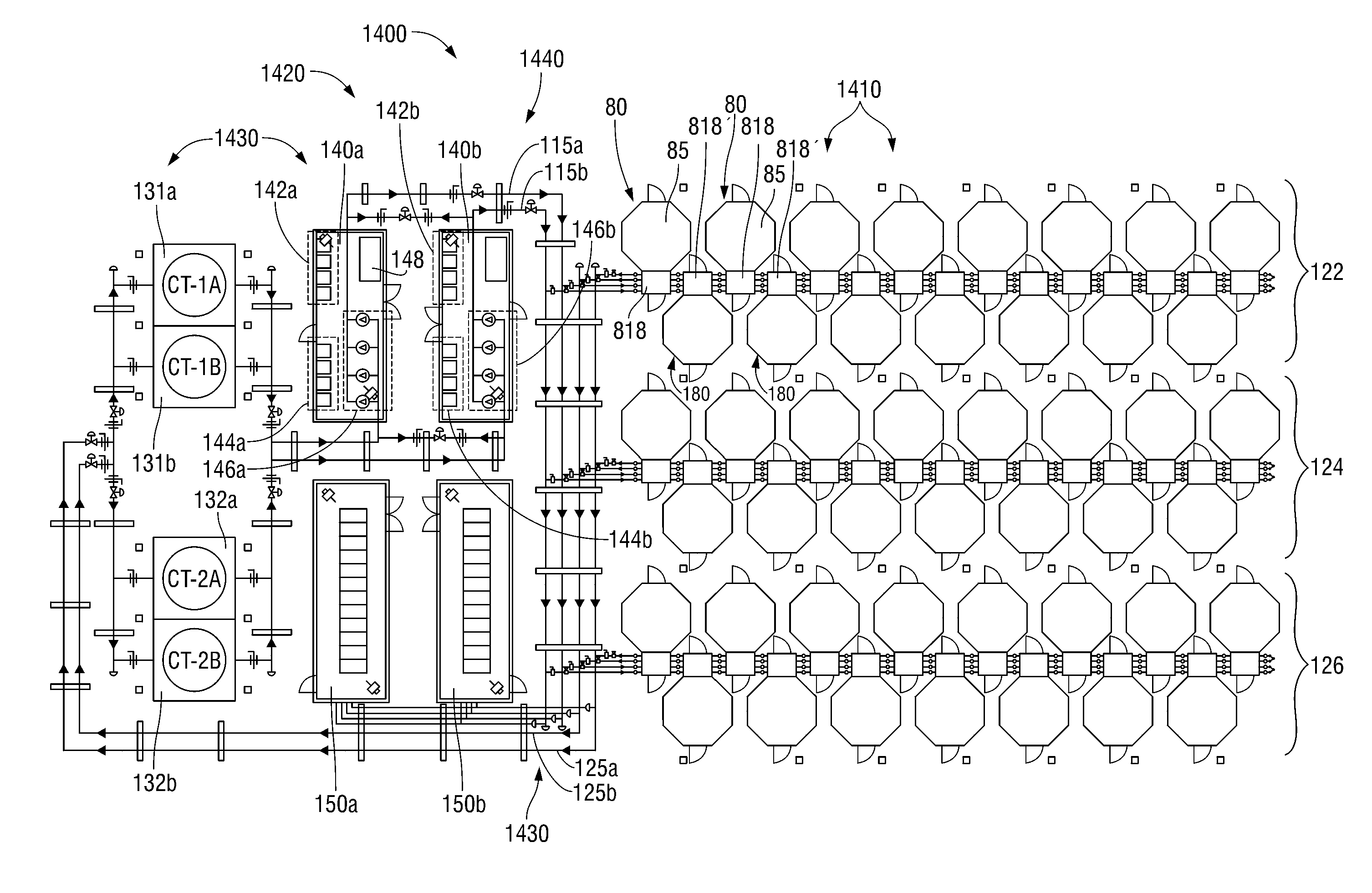
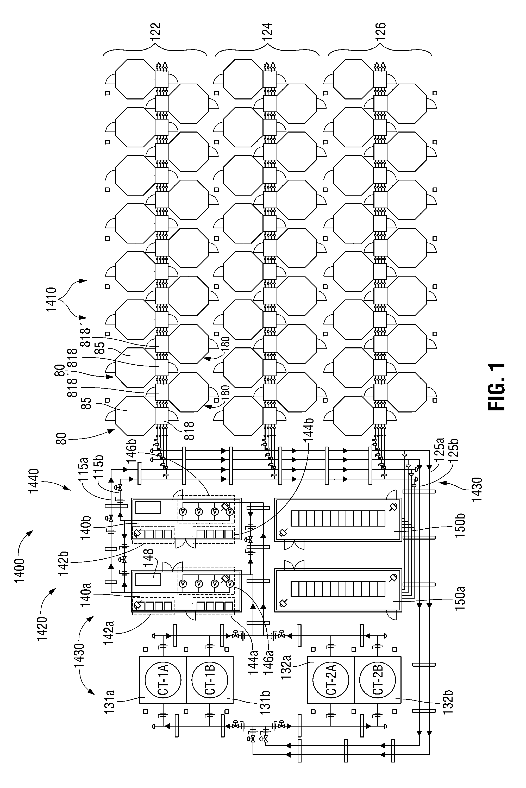
[0059]Embodiments of the presently disclosed close-coupled cooling systems and methods will now be described in detail with reference to the drawings, in which like reference numerals designate identical or corresponding elements in each of the several views.
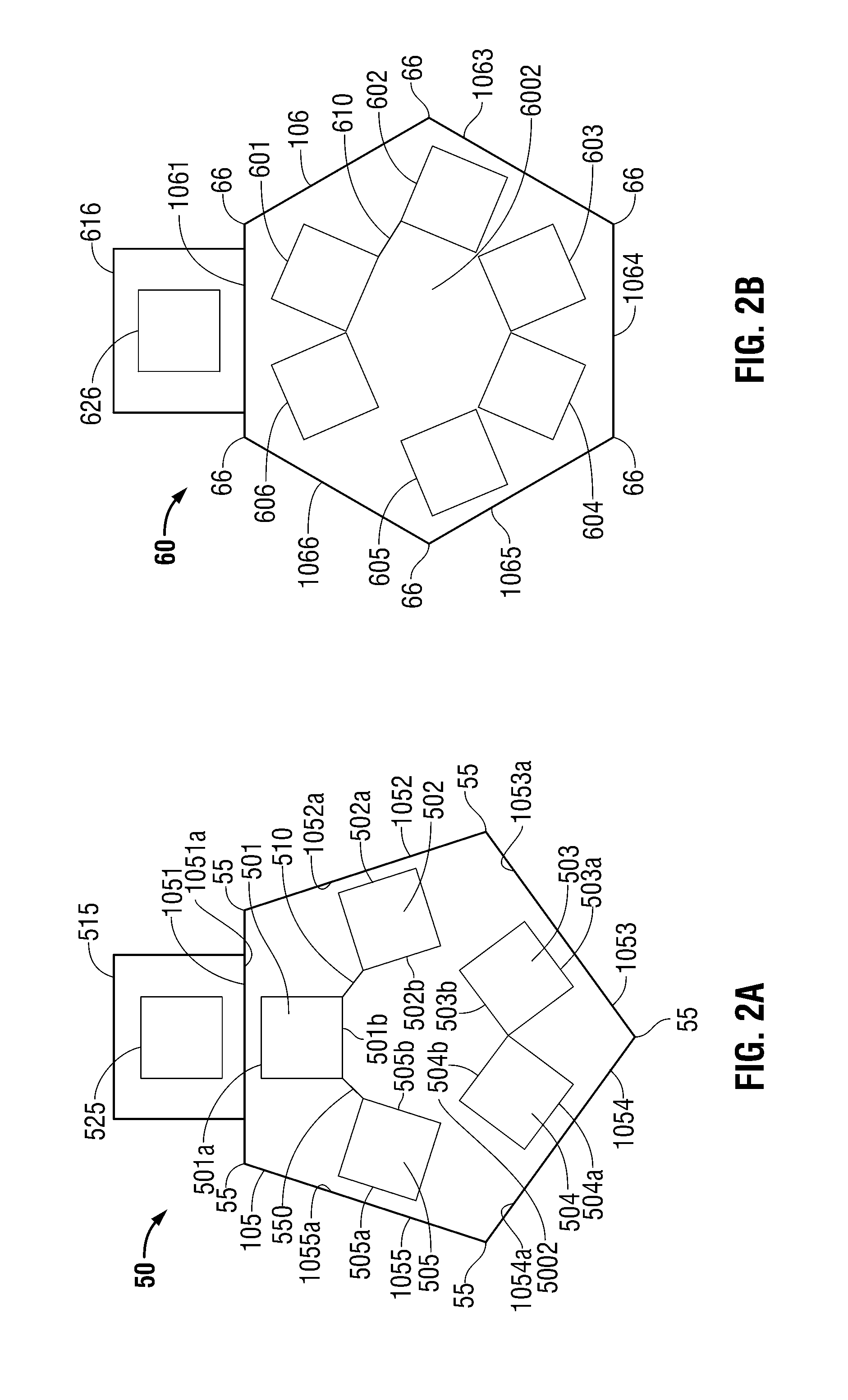
[0060]The present disclosure relates to modular data pods and related support systems for providing energy-efficient, space-saving, and high-density server rack configurations. This modular approach allows for highly efficient use of geometric shapes such as octagonal, hexagonal, and pentagonal shapes for creating a hot aisle and a cold aisle through which air circulates for cooling the server racks. These polygonal shapes allow for maximum energy-efficiency and space-savings using the benefits of both the interior and the exterior angles and sides. The interior pod shape provides a natural circular configuration for positioning server racks. As compared to the prior art, this configuration provides a more efficient way to creat...
PUM
Property
Measurement
Unit
Temperature
aaaaa
aaaaa
Pressure
aaaaa
aaaaa
Level
aaaaa
aaaaa
Abstract
Systems and methods for cooling an inverter of a variable frequency drive that drives a compressor in a cooling system for electronic equipment are disclosed. The system includes a first fluid circuit that cools electronic equipment using a first fluid flowing therethrough and a second fluid circuit that free cools a second fluid flowing therethrough. The second fluid circuit cools the first fluid using the free-cooled second fluid. The system further includes a third fluid circuit that mechanically cools the second fluid using a third fluid flowing therethrough as a function of the wet bulb temperature of atmospheric air. The third fluid circuit includes at least one compressor compresses the third fluid and is driven by a motor coupled to the variable frequency drive. At least a portion of the first fluid flowing through the third fluid circuit is diverted to cool the inverter of the variable frequency drive.
Description
CROSS-REFERENCE TO RELATED APPLICATIONS[0001]This application relates to International Application No. PCT / US2011 / 41710, which was filed on Jun. 23, 2011, published as WO 2011 / 163532 A2 on Dec. 29, 2011, and which claims the benefit of, and priority to, U.S. Provisional Application No. 61 / 357,851, which was filed on Jun. 23, 2010; U.S. Provisional Application No. 61 / 414,279, which was filed on Nov. 16, 2010; U.S. Provisional Application No. 61 / 448,631, which was filed on Mar. 2, 2011; and U.S. Provisional Application No. 61 / 482,070, which was filed on May 3, 2011, the entire contents of each of which is incorporated by reference herein.[0002]This application relates also to International Application No. PCT / US2011 / 067679 which was filed on Dec. 28, 2011, which claims the benefit of, and priority to, U.S. Provisional Application No. 61 / 448,631, which was filed on Mar. 2, 2011; and U.S. Provisional Application No. 61 / 482,070, which was filed on May 3, 2011, the entire contents of each...
Claims
Application Information
Patent Timeline
Application Date:The date an application was filed.
Publication Date:The date a patent or application was officially published.
First Publication Date:The earliest publication date of a patent with the same application number.
Issue Date:Publication date of the patent grant document.
PCT Entry Date:The Entry date of PCT National Phase.
Estimated Expiry Date:The statutory expiry date of a patent right according to the Patent Law, and it is the longest term of protection that the patent right can achieve without the termination of the patent right due to other reasons(Term extension factor has been taken into account ).
Invalid Date:Actual expiry date is based on effective date or publication date of legal transaction data of invalid patent.

