Apparatus and Method For Checking Position and/or Shape of Mechanical Pieces
Inactive Publication Date: 2008-08-14
MARPOSS SPA
6 Cites 5 Cited by
AI-Extracted Technical Summary
Problems solved by technology
As a consequence the dimensions of the sliders and those of the other component parts, that must obviously maintain and improve the high quality and reliability features, are extremely reduced.
If the dimensions of the part to be checked are very small (for example less than a millimeter) and the swinging angle is limited, for example by physical features of the specific application, the limited dynamics of the processed signal may not guarantee th...
Benefits of technology
[0007]An object of the present invention is to provide an optoelectronic apparatus for checking geometrical features of mechanical parts that enable...
Abstract
An apparatus for checking mechanical pieces comprises a base (1), a locking and reference system (31), an optoelectronic measuring system (53), displacement systems (3, 9, 26) and a processing unit (25) for receiving and processing the signals of the optoelectronic system. The displacement systems also enable mutual translation displacements, along a transversal axis, between the optoelectronic system and the piece to be checked. A method of checking foresees to detect signals provided by the optoelectronic system relating to a surface (51′) of the piece in the course of the mutual oscillations, at at least two different transversal positions (A, B), and carry out a processing in order to obtain information relating to a virtual surface (51). The method and the apparatus enable to obtain information relating to the position and/or the arrangement and/or the shape of even very small-dimensioned component parts of hard disk storage units.
Application Domain
Feeler-pin gaugesMechanical counters/curvatures measurements +8
Technology Topic
Virtual surfaceEngineering +3
Image
Examples
- Experimental program(1)
Example
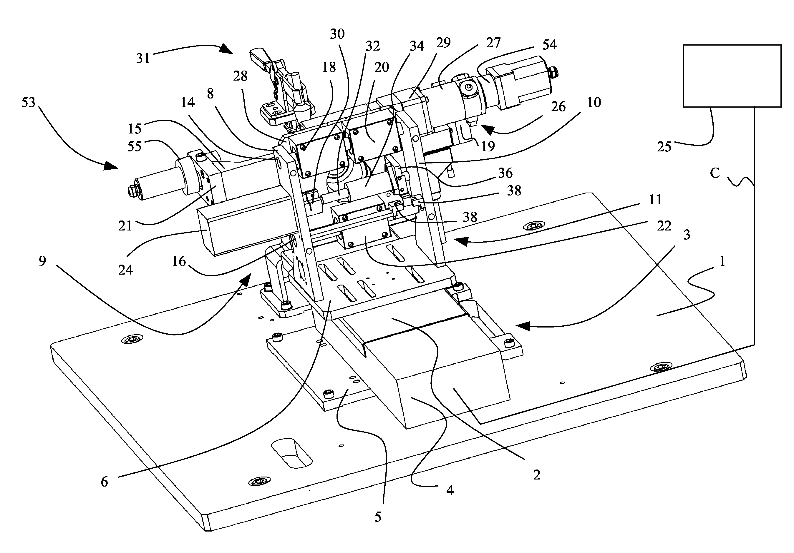
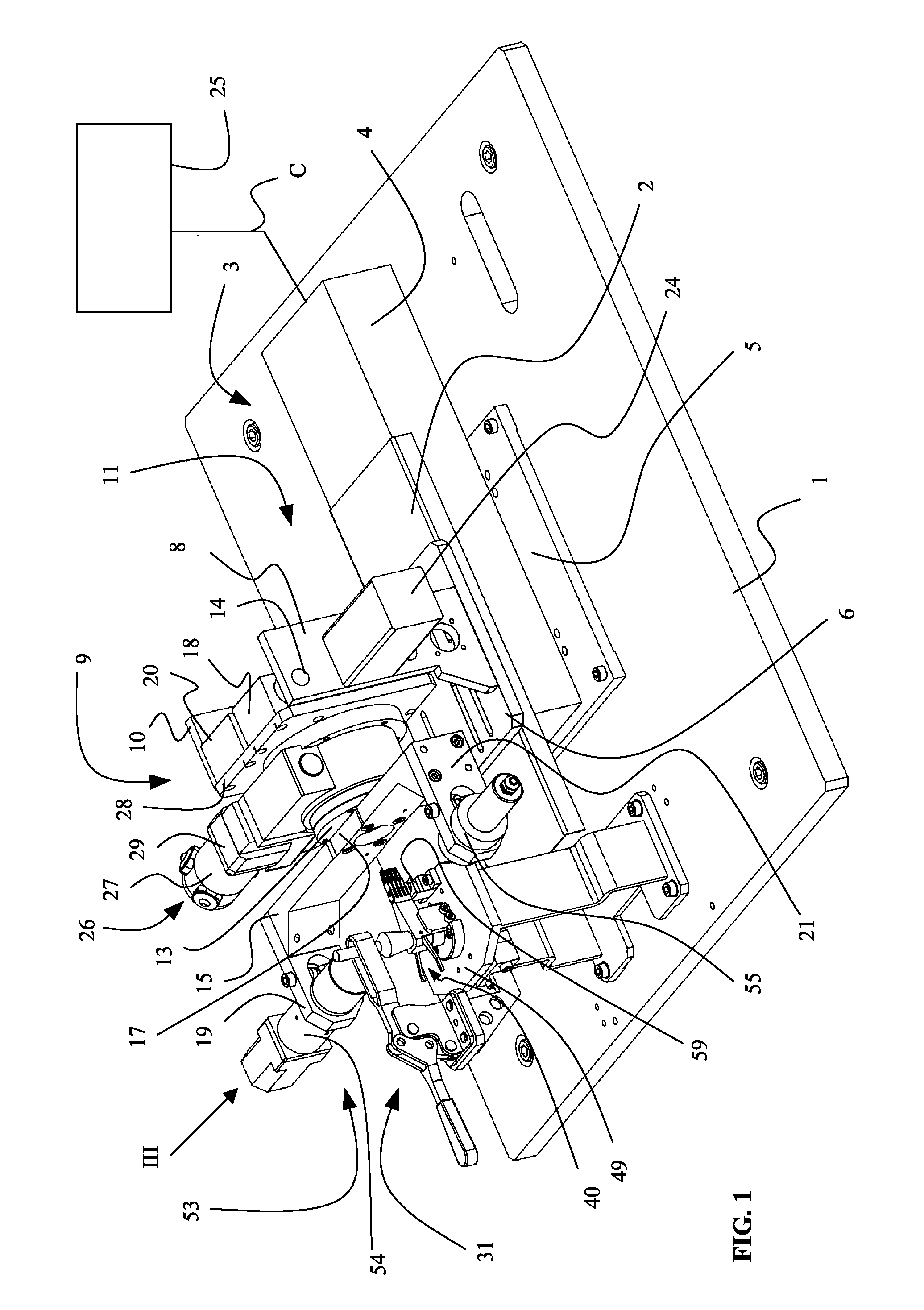
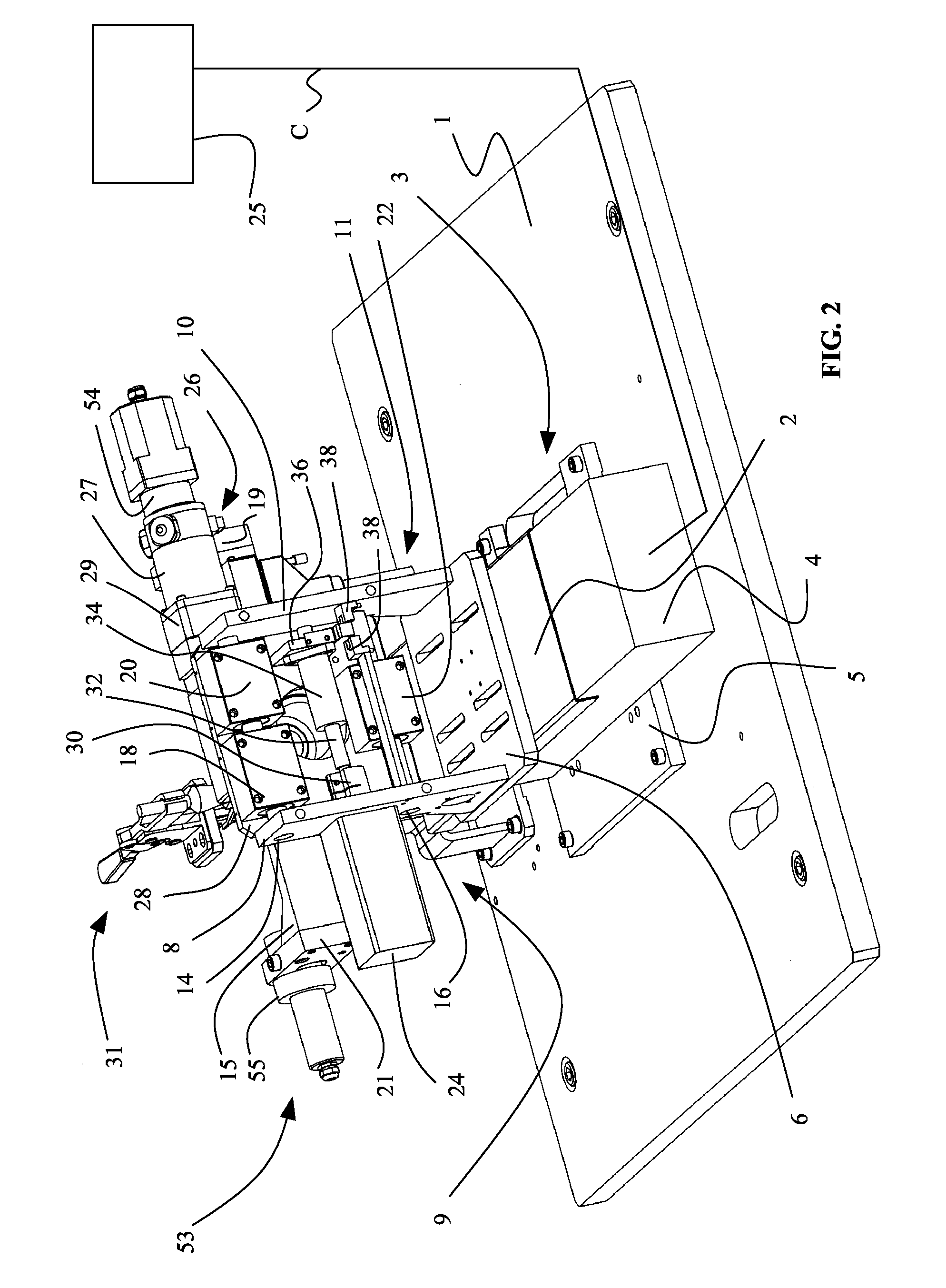
[0018]The optoelectronic apparatus shown in FIGS. 1-2 is utilized for the checking of parts of a mechanical piece with complex shape, more specifically a Head Stack Assembly (“HSA”) 40. The HSA of FIGS. 1-2 is shown in a more detailed, though schematic, way in FIG. 3 and includes an E-block 42 with a plurality of wings 44. Thin plates 46 are coupled to the wings 44 and carry, at free ends, sliders 50. Other details of the HSA, as the read/write heads coupled to the sliders and the gimbals located between thin plates and sliders, are not shown in the figures for reasons of simplicity and clarity. The apparatus shown in FIGS. 1-2 is under many aspects similar to the apparatus described in EP-1029219-B1 (FIG. 1) and includes a base 1 to which there is coupled a displacement system with a longitudinal translation system 3 of a known type that defines a longitudinal axis and includes a support 5 fixed to the base 1 by means of screws. The support 5 carries a protection structure 4 whereupon a longitudinal slide 11 can translate. The protection structure 4 includes component parts of the longitudinal translation system 3, per se known and not shown in the figures, like driving devices with a first electric motor for translating the longitudinal slide 11 along the longitudinal axis by means of a feed screw and detecting devices with a first rotary transducer, or encoder, for providing signals relating to the position of the longitudinal slide 11 with respect to the base 1. The longitudinal slide 11 includes a movable beam 2, that can slide along the protection structure 4, to which there is coupled a rest plate 6 for supporting two stanchions 8, 10. First end portions of two guide spindles 14, 16 are coupled to the stanchion 8, while second end portions are coupled to the stanchion 10. Two component parts with bushings 18, 20 are coupled to the guide spindle 14, while a third component part with a bushing 22 is coupled to the guide spindle 16. The component parts 18, 20, 22 are coupled, for example by means of screws, to a first side of a movable table 28, that is part of a displacement system, more specifically a transversal translation system 9 defining a translation axis that is transversal, more specifically perpendicular, to the longitudinal axis. The transversal translation system 9 includes associated driving devices with a second electric motor 24 coupled to the stanchion 8, other detecting devices with a second transducer (not shown in the figures), and a transmission mechanism including a joint 30, coupled to the motor 24, that carries a worm screw 32 integral with the joint 30 and a threaded component or lead nut 34 coupled to the worm screw 32. A coupling element 36, coupled to the lead nut 34, is fixed to the movable table 28. The second electric motor 24 causes the worm screw 32 to rotate about its axis in either direction and, consequently, the lead nut 34 to translate along the translation axis. As a consequence, the movable table 28 can translate along the guides provided by the spindles 14, 16 with respect to the stanchions 8, 10 of the slide 11. The stanchions 8, 10 also carry position sensors 38 of a known type, as an example of the inductive or optical type, that detect the reaching of limit stop positions of the movable table 28 in the course of the displacement along the translation axis. The position sensors 38 cooperate in a known way with an element integral with the coupling element 36.
[0019]At a second side of the movable table 28 there is coupled, for example by means of screws, a rotary table 13 that is part of a displacement system, more specifically a rotation system 26, and defines a longitudinal axis of rotation. A substantially C-shaped support 15 for detecting devices including an optoelectronic measuring system 53 is fixed, for example by means of screws, at a central part 17 (of the support 15), to the rotary table 13 and carries the component parts of the optoelectronic measuring system 53 at free ends 19, 21. The optoelectronic measuring system 53 is of the known shadow casting type, for example like the one described in EP-1029219-B1, and includes an emitter 54 for generating a beam of light and a receiver 55 for receiving the light and generating corresponding electric signals.
[0020]Moreover, the rotation system 26 includes associated driving devices with a third motor 27 that causes rotations of the rotary table 13 about the longitudinal axis of rotation. Small rotational displacements of the rotary table 13 in a clockwise and counterclockwise direction (swinging) enable the ends 19, 21 of support 15 and, thus, the component parts of the optoelectronic measuring system 53 integral with them to oscillate in a plane Y-Z substantially perpendicular to the axis of rotation of the rotary table 13. Possible oscillations of the support 15 in a clockwise and counterclockwise direction can be limited, in a per se known way that is not shown in the drawings, by suitable adjustable, mechanical references fixed to the slide 11, or by known devices located at the interior of the rotary table 13. Additional detecting devices including a third rotary transducer 29, for providing signals depending on the angular position of the rotary table 13 and thus of the optoelectronic measuring system 53, are coupled to the motor 27.
[0021]The electric motors, the transducers and the component parts of the optoelectronic system 53 are connected, in a known way represented in simplified form in the figures by a conductor C, to a processing unit including power supply, control and display functions, schematically shown in FIGS. 1 and 2 and identified by reference number 25.
[0022]The HSA 40 is fixed to a locking and reference system 31 of a known type. As shown in FIG. 1, the locking and reference system 31, including a worktable 49, is coupled to the base 1, for example by means of screws, and can have different shape and structure, e.g. depending on the dimensions and on the shape of the piece to be checked, as described and illustrated, for example, in EP-1029219-B1.
[0023]FIG. 3 shows some details of the locking and reference system 31, like a reference block 59, fixed to the worktable 49, including a surface 58 that defines a reference plane r for the optoelectronic measuring system 53. A protection element 61 protects the reference block 59 from dust or other foreign matter that may deposit on the surface 58 and hence prevent the optoelectronic system 53 from properly detecting the reference plane.
[0024]The locking and reference system 31 identifies and fixes the position of the HSA 40 to be checked, more specifically with respect to the reference plane r.
[0025]The operation of an apparatus according to the invention for the checking of the sliders 50 of the HSA 40 is now described with reference to FIGS. 3-7.
[0026]The apparatus disclosed in the present invention can be utilized for checking the height and the spatial arrangement or attitude (inclination angles about different axes, or “roll” and “pitch”) of each slider 50 coupled to its associated thin plate 46. As previously mentioned, these features are of importance for a correct read/write process.
[0027]The HSA 40 is fixed to the locking and reference system 31 in such a way that the thin plates 46 lie on planes that are substantially parallel to the longitudinal axis and to the translation axis.
[0028]For the sake of clarity, the operation of the optoelectronic apparatus is hereinafter disclosed by describing first the checking of a slider 50 according to a method that utilizes known parts of the apparatus, and describing then the new method of checking by means of the apparatus according to the invention.
[0029]FIG. 4 shows, in simplified form, the intersection line—on plane Y-Z of a reference system XYZ integral with the optoelectronic system 53—of a substantially plane surface 51 of one of the sliders 50 shown in FIG. 3, corresponding for example to the upper face (obviously, the checking can be carried out in the same way with reference to the lower face and to the associated surface). The surface 51 has transversal dimension b. In such reference system, the X axis is parallel to the longitudinal axis of rotation and lies on the reference plane r, the Y axis is parallel to the beam of light and the Z axis is perpendicular to both.
[0030]In the figure the external sides (or edges) of the surface 51 are indicated by two points, ep and en.
[0031]Translations of the longitudinal slide 11 are controlled by the first electric motor and associated encoder, housed in the structure 4, and they are stopped upon the reaching of a position in which the optoelectronic measuring system 53 is at a transversal section plane S1 (shown in FIG. 3)—lying substantially in the plane of FIG. 4—in which it is required to carry out the checkings of the slider 50.
[0032]The third motor 27 controls small rotation displacements, in a clockwise and in a counterclockwise direction, of the rotary table 13 about the axis of rotation, by making the component parts of the optoelectronic measuring system 53 oscillate substantially in the section plane S1 corresponding to the one of FIG. 4. In the course of such rotation displacements, the optoelectronic measuring system 53 detects the spatial position of the slider 50, more specifically of the associated surface 51, for example with respect to the reference plane r defined by the surface 58 of the reference block 59 and the detected data are processed by the processing unit 25.
[0033]On the basis of the signals provided by the receiver 55 of the optoelectronic system 53 and by the rotary transducer 29, the height zp of the point ep can be defined as a function of the angle of rotation (or swinging) θ of the optoelectronic system 53. Under the hypothesis that the axis of rotation includes the middle point of the surface 51 in the cross-section under consideration shown in FIG. 4, the height zp can be expressed as:
z p ( θ ) = b 2 × sen ( θ ) + z p 0 ( 1 )
where zp0 is the height z of the point ep at the angle θ=0.
[0034]The slider 50 and the optoelectronic system 53 perform small mutual oscillations with respect to an initial position, the oscillations being included between an angle −θk and an angle +θk. As known, for small angles the sine of the angle substantially corresponds to the value of the angle in radians and the equation (1) can be simplified as follows:
z p ( θ ) = b 2 × θ + z p 0 ( 2 )
[0035]An analogous equation (3) can be considered for the point en:
z n ( θ ) = - b 2 × θ + z n 0 ( 3 )
where zn0 is the height z of the point en at the angle θ=0.
[0036]On a plane θ-Z shown in FIG. 5, the equations (2) and (3) are represented by straight lines Rp and Rn that meet at a point of intersection I. It is assumed that the system has previously been properly calibrated, so that the condition whereby the beam of light of the optoelectronic system 53 is parallel to the reference surface r corresponds to the value θ=0 and the height of the reference plane r corresponds to the value z=0.
[0037]The point I represents the condition according to which the point ep and the point en have identical height zs, that is to say they are both aligned to the beam of light of the optoelectronic system 53. The value zs indicates the height of a central portion of the surface 51 with respect to the plane r. The angle θI corresponding to this condition represents the inclination φR of the surface 51 of the slider 50 about the X axis (see FIG. 4) with respect to the reference plane r, and is defined as roll angle. Such angle contributes to define the spatial arrangement or attitude of the slider 50 and, in order to guarantee a proper read/write process of the head over its associated disk, it must have a substantially null value.
[0038]In actual fact, the signal provided by the optoelectronic system 53 is affected by noise and the corresponding curve representing the height z of the points ep and en depending on the angle θ does not coincide with portions of the straight lines Rp and Rn. Moreover, there is a greater influence of the optical noises at the point of intersection I, when beam of light and surface 51 are substantially aligned and signals relating to the opposite surfaces of the slider 50 (upper and lower surfaces) are mixed up and hardly distinguishable. The curve S shown in FIG. 5 shows a typical trend of the signal that has actually been provided.
[0039]Owing to the above mentioned noise, the point of intersection I is obtained as the intersection of straight lines obtained by processings including linear regression on the basis of values of the signals provided by the optoelectronic system 53 in limited swinging intervals in which the noises are expectantly negligible. More specifically, the first straight line is obtained through regression processing of the data relating to the point ep detected in a first limited interval. The data used for the processing are those with greater z, that is to say farthest away from point I to be determined (to which there correspond angular values in the interval θ1-θ2 closer to +θk), data that are presumably less affected by noise. A similar processing is performed for the second straight line, that is obtained from data relating to the point en detected in a second interval, more specifically the data with greater z (to which there correspond angular values in the interval θ3-θ4 closer to −θk).
[0040]Upon the decrease of the transversal dimension b of the surfaces 51 of the sliders 50 and at identical swinging angle, the variation of light intercepted by the slider 50 and corresponding variations of the dimension z decrease. In the graph shown in FIG. 5, this implies a minor slope of the straight lines Rp and Rn and a decrease of the variability interval of z in the detected intervals (θ1-θ2 and θ3-θ4). In other terms, the “dynamics” of the signal provided by the receiver 55 decreases.
[0041]For example, in the case of sliders with transversal dimension b in the order of one millimeter and relative rotations between the slider 50 and the optoelectronic system 53 that do not exceed 10°, the height of the useful intervals (shown in simplified form and identified by references Δz1 and Δz2 in FIG. 5) is of few tens of μm.
[0042]Therefore, if the transversal dimension b of the slider to be checked is very small, the amplitude of the interval of the reliable data can be too small and not allow sufficiently accurate and repeatable processings. With reference to the specific processing, the determining of the point of intersection I, and thus of the dimension zs and of the roll angle θI, can be difficult.
[0043]In order to broaden the variation interval of z, it can be envisaged to increase the amplitude of the rotation between the piece 40 and the optoelectronic system 53. However, this solution is not always possible, for example in consideration of the mechanical layout dimensions of the apparatus in the course of the rotation, of the possibility that the slider 50 be “hidden” to the optoelectronic system 53 by other component parts in the course of the rotation, or by problems bound to the focusing of the optoelectronic system 53.
[0044]A method of checking performed by the apparatus according to the present invention foresees that once the position of the slide 11 along the longitudinal axis is defined, in addition to the oscillation displacements of the rotary table 13, there be also controlled displacements along the translation axis of the movable table 28, to which the rotary table 13 is coupled, between a first and a second transversal end position. The displacements of the table are controlled by the motor 24, the previously described transmission mechanism and the position sensors 38.
[0045]FIG. 6 shows, in simplified form by a continuous line, the cross section of the surface 51 of the slider 50 on the same section plane S1 of FIG. 4 at three positions: a first transversal end position A, a second central position, and a third transversal end position B in a reference system XYZ integral with the optoelectronic system 53 and defined as in FIG. 4.
[0046]As in the previously described case, reference is hereinafter made to the surface 51 of the upper face as an example only, and the checking can be carried out in the same way with reference to the lower face and to its associated surface.
[0047]With respect to the reference system XYZ, the slider 50 is translated from the central position along the Y axis both in a positive and in a negative sense, for example by an identical amount ΔY, towards the transversal end positions A and B that are consequently located at identical distances and at opposite sides with respect to the transversally centered position. By virtue of the translation displacements along the Y axis, the surface 51 forms an identical roll angle φR with the Y axis both in the central position, and in the transversal positions A and B. The relative translation and the swinging between the slider 50 and the reference system XYZ are implemented, in the embodiment shown in FIGS. 1 and 2, by translation and rotation displacements of the optoelectronic system 53 that defines the reference system. At each of the transversal positions A and B, there are performed one or a plurality of swinging cycles between the optoelectronic system 53 and the slider 50, and acquired values relating to the spatial position of the points ep1, en1 and ep2, en2, that define the ends of the surface 51 in the transversal positions A and B, respectively. The graph of FIG. 7 shows the theoretical trend of values z detected by the optoelectronic system 53 as the swinging angle θ varies and representing the position of the points ep1, en1 and ep2, en2. Although the optoelectronic system 53 typically does not detect the ending edges of the surface 51 when the latter is in a central position, for reasons of clarity the graph of FIG. 7 also shows the theoretical trend of values z as a function of the swinging angle θ of the points ep and en, that is to say of the ends of the surface 51 in central position.
[0048]The detecting of values relating to the surface 51 of the slider 50 at the transversal end positions A and B enables to acquire the spatial position of a fictitious, “virtual” slider, whose upper face (in the specific example) has virtual surface 51′ with transversal dimension bapp (longer than that of the real slider) and with ending points ep1, en2, that forms an “apparent roll” angle φRapp with Y axis.
[0049]The value of the apparent roll angle corresponds to the coordinate θapp of the point Iapp of intersection of the theoretical straight lines of FIG. 7 representative of the ending points ep1, en2. The height of a central portion of the surface 51′ of the virtual slider corresponds to the coordinate zs of the point Iapp.
[0050]The angle φRapp that the virtual surface 51′ forms with the Y axis can be expressed as:
φRapp=arcsen(Δzapp/bapp) (4)
where Δzapp is defined as difference in height between the point ep1 and the point en2.
[0051]In an entirely identical way, the angle φR that the surface 51 of the slider 50 forms with the Y axis can be expressed as:
φR=arcsen(Δzreal/b) (5)
where Δzreal is defined as difference in height between the point ep and the point en.
[0052]As the swinging angles are small, the arcsen function of the angle substantially corresponds to the angle and the equations (4) and (5) can be simplified to obtain the following equations (6) and (7), respectively:
φRapp≅Δzapp/bapp (6)
and
φR≅Δzreal/b (7)
[0053]As the slider 50 performs translation displacements along the Y axis, the points ep1 and ep are of identical height, as well as the points en2 and en. As a consequence, their differences are identical, that is:
Δzapp=Δzreal (8)
and the roll angle φR can be expressed as:
φR=φRapp×bapp/b (9)
[0054]The graph of FIG. 7 also shows the point I, of coordinates θI and zs, defined by the intersection of the theoretical straight lines that represent the points ep and en. Positions of points I and Iapp in FIG. 7 show that the surface 51 of the slider 50 and the virtual surface 51′ lie at the same height zs.
[0055]The advantages obtainable by the present invention are evident, more specifically those consequent to the possibility of mutually translating the slider and the optoelectronic system 53 along Y axis, and acquiring values relating to the position of the surface 51 at two positions A and B, that are distant, for example, ΔY from the central position in one sense or in the other. In fact, the theoretical straight lines representative of the points ep1 and en2, i.e. of the ends of the virtual surface 51′, have greater angular coefficient (in absolute value) than the theoretical straight lines representative of the points ep and en, respectively. This enables to increase, for an identical angular interval, the variability interval of the corresponding values detected by the optoelectronic system 53 and thus obtain more reliable data for processing the regression straight lines. More specifically, in the interval θ3-θ4, the variability interval of z along the straight line that represents the point en2 (indicated in FIG. 7 by the reference Δznapp) is greater than the variability interval of z along the straight line that represents the point en (reference Δzn). In the same way, in the interval θ1-θ2, the variability interval of z along the straight line that represents the point ep1 (indicated by the reference Δzpapp) is greater than the variability interval of z along the straight line that represents the point ep (reference Δzp).
[0056]In other words, the displacing of the ends of the surface 51 of the slider 50 away from the axis of rotation of the optoelectronic measuring system 53, obtained by means of mutual translations along the Y axis in a sense and in the other, enables to amplify the dynamics of the signal provided by the receiver 55 without the use of electric or electronic amplification means.
[0057]In this way, both the height zs and the roll angle φR can be determined—the latter through a very simple mathematical process—with great accuracy and repeatability even in the case of pieces with very small transversal extension.
[0058]The present invention makes it possible to check even other surface features of the sliders 50 as, for example, the pitch, by carrying out two subsequent swinging cycles at two distinct section planes S1 and S2 (shown in FIG. 3).
[0059]In the example that refers to the surface 51, after the first checking performed at section plane S1, the optoelectronic system 53 is displaced along the longitudinal axis by means of the translation system 3 and stopped at the desired section plane S2. Thus the pitch value is obtained by dividing the difference in height of the surface 51 of the slider 50 taken into consideration obtained at S1 and S2 by the distance between the section planes S1 and S2.
[0060]Equivalent results can be obtained by locking the optoelectronic system 53 with respect to the base 1 and by making the locking and reference system 31, that carries the piece to be checked, transversally translate and rotate about the axis of rotation. It is likewise possible that some displacements be performed by the component part carrying the slider 50 and other displacements be performed by the optoelectronic system 53.
[0061]In substance the present invention covers many embodiments according to which the mechanical piece to be checked and the optoelectronic measuring system 53 can perform in any event mutual swinging displacements about the longitudinal axis and translation along the translation axis.
[0062]Relative swinging displacements between the mechanical piece and the optoelectronic system 53 typically occur just at the transversal end positions A and B in which the position of the edges of the surface 51 of the slider 50 is acquired, but they can also be implemented in a continuous way in the course of the transversal displacement from one position to the other.
[0063]As hereinbefore stated, in the present description of a checking method according to the invention it has been assumed, for the sake of providing simplicity and clarity to the exposition, that when the slider 50 lies in a central position on the translation axis, the middle point of the surface 51 in the considered section lies on the longitudinal axis of rotation. Even where this basic condition does not physically occur, it is in any case always possible to refer to it for implementing the checking method according to the invention and to take into account and to compensate for the different arrangement by means of simple known mathematical processes, typically implemented by software.
[0064]The present invention also covers checking methods according to which the acquisitions relating to the ends of the surface 51 of the slider 50 occur at transversal end positions A and B that are not equally equidistant with respect to the central position. In other words, the optoelectronic system 53 and the slider 50 can be made to mutually translate along the Y axis by a certain amount in a positive sense, and by a different amount in a negative sense.
[0065]Moreover, it is possible to simultaneously check a plurality of pieces, for example by detecting the edges of the surfaces 51 of different sliders 50 coupled to a same E-block in the course of the swinging.
[0066]As hereinbefore described, the apparatus and the method according to the present invention are particularly useful for checking pieces with small dimensions, as sliders of HSA, but can certainly be utilized for checking even other parts of the HSA, as for example the wings 44 and the thin plates 46 or any other mechanical piece with at least one substantially plane surface.
[0067]An apparatus and a method according to the invention provide great advantages even in the checking of mechanical pieces with larger dimensions. In fact, the checking of mechanical pieces of any dimension is improved by the widening of the dynamics of the signals to be processed, this widening being advantageously achieved without the utilization of electric or electronic amplification means.
PUM


Description & Claims & Application Information
We can also present the details of the Description, Claims and Application information to help users get a comprehensive understanding of the technical details of the patent, such as background art, summary of invention, brief description of drawings, description of embodiments, and other original content. On the other hand, users can also determine the specific scope of protection of the technology through the list of claims; as well as understand the changes in the life cycle of the technology with the presentation of the patent timeline. Login to view more.