Starter having excessive-torque-absorbing device

Inactive Publication Date: 2008-08-21
DENSO CORP
View PDF4 Cites 7 Cited by
  • Summary
  • Abstract
  • Description
  • Claims
  • Application Information

AI Technical Summary

Benefits of technology

[0013]The rotational disk is formed integrally with an internal gear of the planetary gear speed reduction device. The internal gear engaging with the planetary gears has to have a hardness comparable to a hardness of the planetary gears, while a portion contacting the fixed disk must have a good abrasion-resistant property. To give the rotatable disk these properties, it is subjected to a treatment of soft nitriding. In addition, a confined grease space is formed

Problems solved by technology

Thus, an excessive torque is absorbed by the device.
This may cause seizing between the fixed disks 120 and the rotatable disks 110, making a slipping torque in the laminated body

Method used


Image

  • Starter having excessive-torque-absorbing device
  • Starter having excessive-torque-absorbing device
  • Starter having excessive-torque-absorbing device

Examples


Example

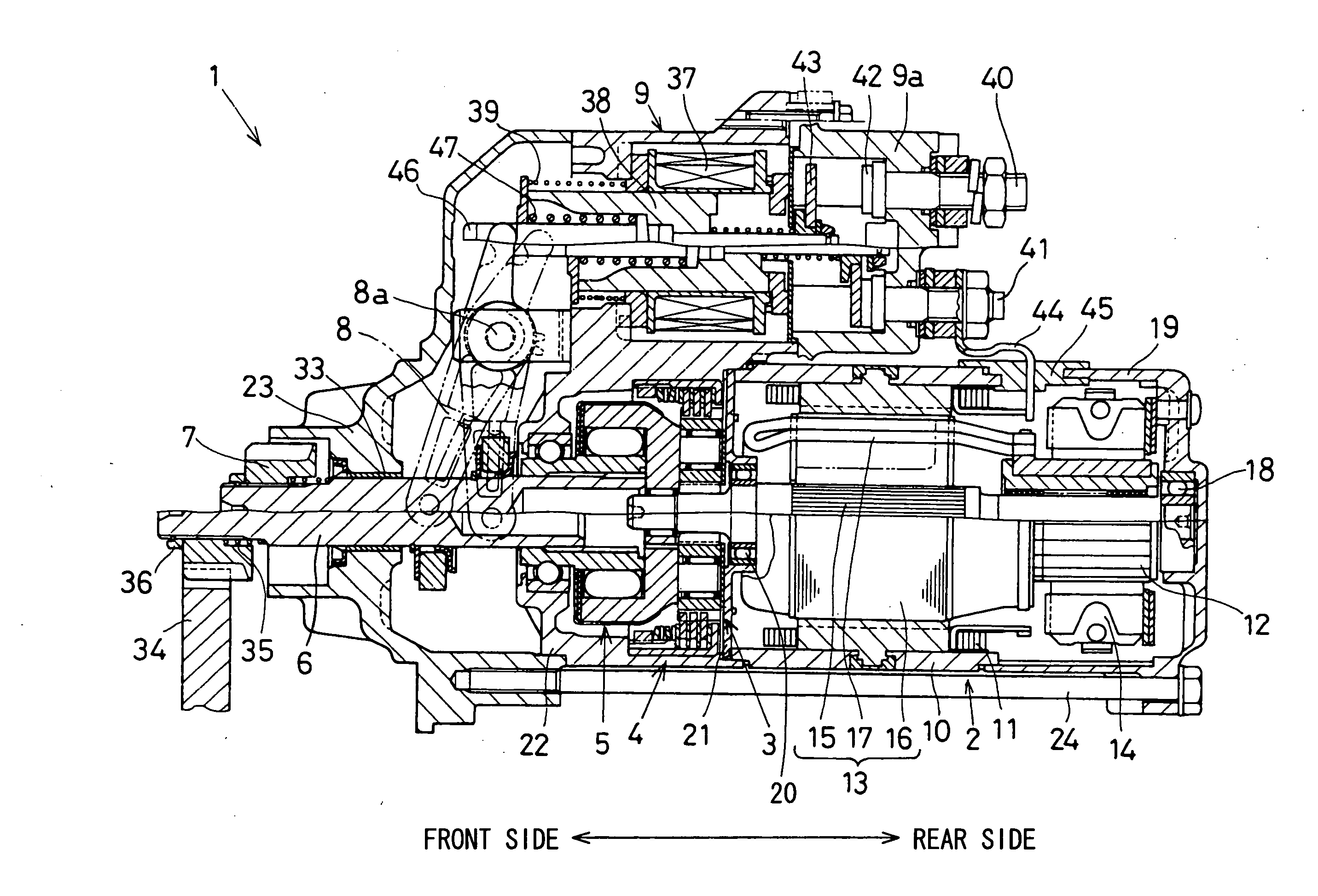
[0032]A first embodiment of the present invention will be described with reference to FIGS. 1-8. First, referring to FIG. 3, an entire structure of a starter 1 in which an excessive-torque-absorbing device 4 is installed. The starter 1 includes: an electric motor 2 generating a rotational torque; a planetary gear speed reduction device 3 for reducing a rotational speed of the electric motor 2; an excessive-torque-absorbing device 4 for absorbing an excessive torque in a starting operation; an output shaft 6 connected to the planetary gear speed reduction device 3 via a clutch 5; a pinion gear 7 supported on the output shaft 6; and an electromagnetic switch 9 forming a circuit for turning on the electric motor 2.

[0033]The electric motor 2 is a known direct current motor composed of a yoke 10 forming a magnetic circuit, field coils 11 disposed in the yoke 10, an armature 13 having a commutator 12, brushes 14 slidably contacting the commutator 12 and other components. It is possible to...

Example

[0054]A second embodiment of the present invention is shown in FIG. 9. In this embodiment, the gap 48d formed on the circular rear end portion of the cylindrical casing 48 is modified to a tapered form. Other structures and functions are the same as those of the first embodiment. The pushing plate 51 may be modified to a form shown in FIG. 10. In the pushing plate shown in FIG. 10, a step for forming the gap 51a is formed by stamping.

Example

[0055]A third embodiment of the present invention is shown in FIG. 11. In this embodiment, another pushing plate 55 is disposed between the rear fixed disk 49B and the circular rear end portion 48a of the cylindrical casing 48. The outer diameter of the pushing plate 55 is made smaller than the outer diameter of the fixed disk 49, thereby forming a gap 55a that corresponds to the gap 48d of the first embodiment. On the outer periphery of the pushing plate 55, projected portions 55b engaging with the depressions 48b of the cylindrical casing 48 are formed. The pushing plate 55 is prevented from rotating and moving in the radial direction by the projected portions 55b. Other structures and functions of the third embodiment is the same as those of the first embodiment.


PUM


Abstract

A starter for cranking an internal combustion engine includes a device for absorbing a rotational torque exceeding a predetermined level. In this device, a laminated body composed of fixed disks and the rotatable disks is used. A frictional force in the laminated body is preset by a spring member pressing the laminated body in the laminated direction. To avoid concentration of the pressing force to a position where the spring force is imposed, a certain gap is formed between the spring member and the laminated body. To give a proper surface hardness to an internal gear portion of the rotatable disk and to give an abrasion-resistive property to a portion contacting the fixed disk, the rotatable disk is subjected to soft nitriding treatment. Thus, a stable frictional force is secured in the laminated body, and a long life of the excessive-torque-absorbing device is realized.

Description

CROSS-REFERENCE TO RELATED APPLICATIONS[0001]This application is based upon and claims benefit of priority of Japanese Patent Applications No. 2007-39849 filed on Feb. 20, 2007 and No. 2007-61937 filed on Mar. 12, 2007, the contents of which are incorporated herein by reference.BACKGROUND OF THE INVENTION[0002]1. Field of the Invention[0003]The present invention relates to a starter for cranking an internal combustion engine, the starter having an excessive-torque-absorbing device.[0004]2. Description of Related Art[0005]An example of an excessive-torque-absorbing device used in a starter is disclosed in JP-A-2005-113816. A relevant portion of this device is shown in FIGS. 15 and 16 attached hereto. Fixed disks 120 and rotatable disks 110 are alternately laminated to form a laminated body. The laminated body is contained in a cylindrical casing 100, and pushed in the laminated direction by disk springs 130 to thereby control a frictional force between the fixed disks 120 and the rot...

Claims


Application Information

Patent Timeline
IPC IPC(8): F02N15/06
CPCF02N15/025Y10T74/137F02N2300/104F02N15/10F02N15/02F02N11/00H02K7/10
Inventor KAJINO, SADAYOSHINAWA, YUKIO
Owner DENSO CORP
Why Eureka
Try Eureka