Atmosphere replacement apparatus, substrate transport apparatus, substrate transport system, and efem

Active Publication Date: 2015-05-14
SINFONIA TECHNOLOGY CO LTD
View PDF2 Cites 5 Cited by
  • Summary
  • Abstract
  • Description
  • Claims
  • Application Information

AI Technical Summary

Benefits of technology

[0035]It is possible to configure as an effective EFEM capable of transferring between a FOUP and a processing apparatus, while maintaining good properties on the surface of a wafer, by configuring as an EFEM that comprises the substrate transport apparatus, and a housing for covering the substrate transport apparatus, wherein the substrate is a wafer, and a transfer position for transferring a substrate is set adjac

Problems solved by technology

In other words, the air atmosphere has a possibility of adhesion of moisture and oxygen to the surface of a substrate, causing corrosion and oxidation.
Further, when a corrosive gas or the like used in the processing apparatus remains on the surface of a wafer, it may cause corrosion of a wiring material on the wafer surface and deterioration in yield.
To avoid such a problem, as in the FOUP, when the atmosphere replacement apparatus is provided to make a nitrogen atmosphere inside the wafer transport chamber, since the volume of the wafer trans

Method used


Image

  • Atmosphere replacement apparatus, substrate transport apparatus, substrate transport system, and efem
  • Atmosphere replacement apparatus, substrate transport apparatus, substrate transport system, and efem
  • Atmosphere replacement apparatus, substrate transport apparatus, substrate transport system, and efem

Examples


Example

First Embodiment

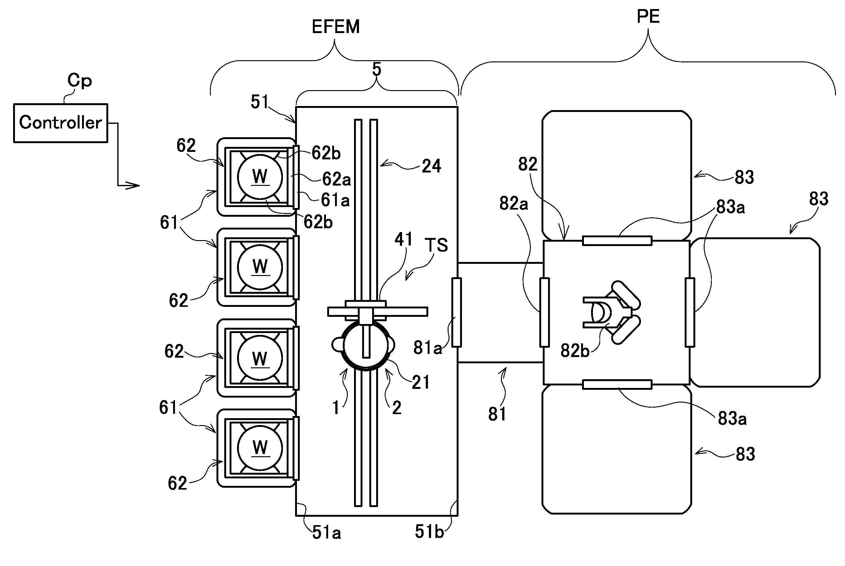
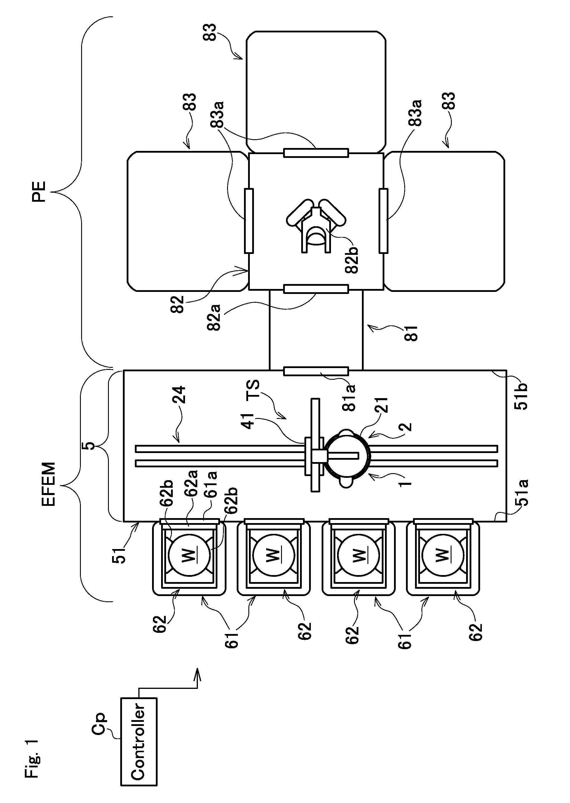
[0072]As shown in FIG. 1, an atmosphere replacement apparatus 1 of a first embodiment configures a wafer transport apparatus 2 or a substrate transport apparatus, and a wafer transport system TS or a substrate transport system. A wafer transport chamber 5 is substantially closed by a housing 51 surrounding the apparatus or system. A plurality of load ports 61 (four in the drawing) is provided adjacent to one wall surface 51a of the housing. The load ports and the wafer transport system TS configure an EFEM. The drawing schematically shows the state that a FOUP 62 is placed on the load port 61. Each load port 61 has a door 61a. As the door 61a moves in conjunction with a lid 62a of the FOUP 62, the FOUP 62 is opened to the wafer transport chamber 5. In the FOUP 62, a plurality of placing portions 62b for supporting one wafer W in pairs is provided in the vertical direction. By using them, a plurality of wafers W can be stored. A nitrogen gas can be filled in the FOUP ...

Example

Second Embodiment

[0114]FIG. 16 is a schematic view showing an atmosphere replacement apparatus 101 of the second embodiment. Also in this case, the atmosphere replacement apparatus 101 constitutes the wafer transport system TS as a substrate transport system, and the wafer transport apparatus 2 as a substrate transport apparatus. In the drawing, the same parts as those in the first embodiment are denoted by the same reference numerals, and the explanation thereof is omitted.

[0115]In the embodiment, the wafer transport apparatus 2 is the same as that explained in the first embodiment, except the structure of the atmosphere replacement apparatus101.

[0116]FIG. 16(a) schematically shows the positional relationship of the wafer transport system TS when viewed from a direction that the guide rail 24 (see FIG. 1) constituting the wafer transport apparatus 2 extends.

[0117]The atmosphere replacement apparatus 101 is supported in a state being suspended from a ceiling surface 51 provided in a...

Example

Third Embodiment

[0122]FIG. 17 schematically shows a configuration of a wafer transport system TS in the third embodiment. In the drawing, the same parts as those in the first and second embodiments are denoted by the same reference numerals, and the explanation thereof is omitted. The wafer transport system TS is a modified from the structure of the wafer transport apparatus 202 by using the atmosphere replacement apparatus 101 explained in the second embodiment.

[0123]In particular, a disk-shaped cover receiving member 225 is provided on the base 221 that constitutes a wafer transport apparatus 202 and supports a transport arm 22. The cover receiving member 225 has a diameter slightly larger than the cover 103 in a plan view to enable to substantially close the internal space S in cooperation with the cover, when the cover 103 moves downward, and an open end 132a of a wall part 132 in the cover 103 approaches the upper surface 225a of the cover receiving member 225. Thus, it is poss...


PUM


Abstract

The present invention provides an atmosphere replacement apparatus capable of replacing the atmosphere on the surface of a wafer with a small amount of gas. The apparatus is configured to have a cover capable of facing and covering the wafer to be transported, and a gas supply means that supplies gas having properties different from a surrounding atmosphere from the cover, and replaces the atmosphere on the surface of the wafer by the gas.

Description

CROSS-REFERENCE TO RELATED APPLICATIONS[0001]This application claims priorities of Japanese Patent Application No. 2013-233572 filed on Nov. 11, 2013 and Japanese Patent Application No. 2013-233573 filed on Nov. 11, 2013. The contents of the application are incorporated herein by reference in their entirety.BACKGROUND OF THE INVENTION[0002]1. Field of the Invention[0003]The present invention relates to an atmosphere replacement apparatus capable of replacing an atmosphere around a substrate during transportation, a substrate transport apparatus, a substrate transport system, and an Equipment Front End Module (EFEM).[0004]2. Description of the Related Art[0005]Conventionally, production of semiconductors has been carried out by various processing steps performed on a wafer as a substrate. In recent years, circuit miniaturization and high integration of elements have been increasingly promoted. It has been required to maintain a high level of cleanliness around a wafer to prevent adhe...

Claims


Application Information

Patent Timeline
IPC IPC(8): F26B25/00H01L21/677
CPCF26B25/003H01L21/67772H01L21/67742H01L21/67389H01L21/6732H01L21/67739
Inventor SEGAWA, MIKIOTANIYAMA, YASUSHIKAWAHISA, SHINNATSUME, MITSUO
Owner SINFONIA TECHNOLOGY CO LTD
Why Eureka
Try Eureka