Device and method of standby lubrification for an engine

Active Publication Date: 2008-08-21
SN DETUDE & DE CONSTR DE MOTEURS DAVIATION S N E C M A
View PDF8 Cites 16 Cited by
  • Summary
  • Abstract
  • Description
  • Claims
  • Application Information

AI Technical Summary

Benefits of technology

[0009]The problem of the present invention is therefore to provide an independent standby lubrication for one engine comprising a main oil lubrication system in the event that this lubrication system fails. This standby lubrication must be provided with a minimal weight penalty, a period of use limited only by the avail

Problems solved by technology

In the event of a failure of the lubrication system, the engine risks being damaged to the point of stopping.
In certain applications, such an inopportune shutdown may be particularly dangerous and particular measures are taken to prevent it.
This standby lubrication device accordingly increases the volume of oil of the main lubrication system, and therefore the weight of the engine, but without having a use except for a possible failure of the main lubrication system.
In addition, its use is limited in time.
Nev

Method used


Image

  • Device and method of standby lubrification for an engine
  • Device and method of standby lubrification for an engine

Examples


Embodiment Construction

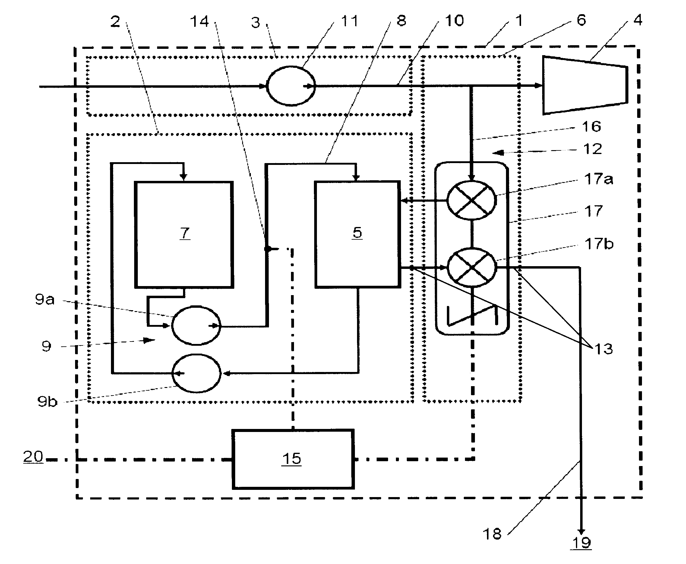
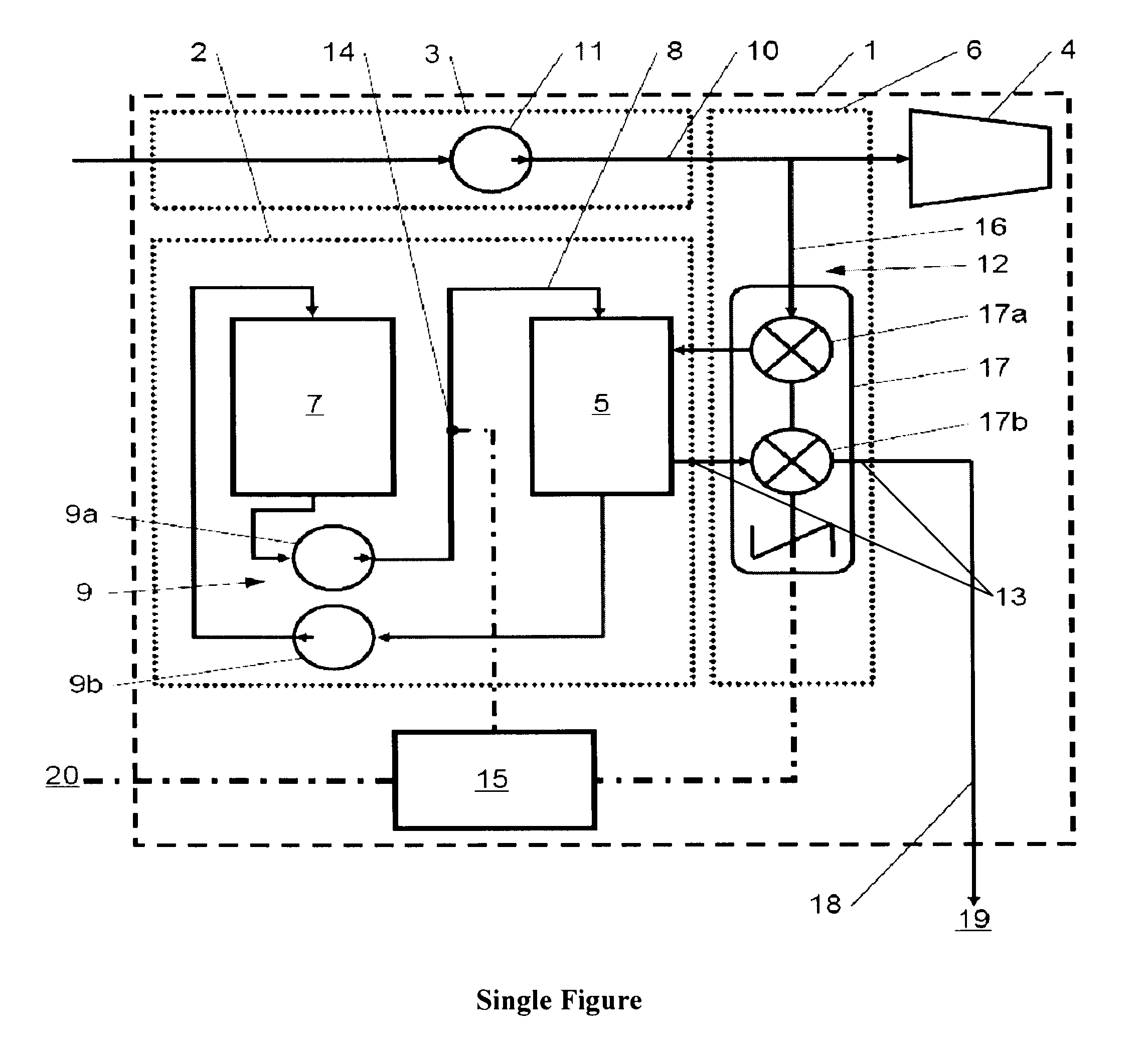
[0011]According to the invention, the failure of the lubrication system is detected and, in response to the detection of this failure, at least one portion of the fuel fluid of the engine is tapped off to lubricate at least one engine element.

[0012]Although lubrication systems have been proposed, for example in U.S. Pat. No. 5,568,984, to lubricate and if necessary cool an engine with the fuel fluid of the latter, such lubrication systems, which are used in particular in jet engines used for the propulsion of missiles, are designed to lubricate the engine in a normal situation and not in the event of failure of another lubrication system. On the basis of these publications, it would not therefore have been evident for those skilled in the art to apply this solution to solve the problem of standby lubrication in the event of failure of a main lubrication system. Furthermore, these systems of lubrication with a fuel fluid in a normal situation make it possible to ensure only a modest ...


PUM


Abstract

The invention relates to a standby lubrication method for an engine 1 in the event of the failure of a main lubrication system 2 of this engine 1, in which said failure is detected and, in response to the detection of this failure, at least one portion of a fuel fluid of the engine 1 is tapped off to lubricate at least one element of the engine 1. The invention also relates to a standby lubrication device 6 for an engine 1 comprising a main lubrication system 2, said standby lubrication device 6 comprising means for detecting a failure of the main lubrication system 2, means 12 for tapping off at least a portion of a fuel fluid of the engine 1 in order to direct it to at least one element of the engine 1 intended to be lubricated, and control means 15 capable of being connected to said tapping and detection means 12, in order to carry out the standby lubrication method.

Description

[0001]The present invention relates to a device and method for the standby lubrication of an engine, and more particularly for an engine of the gas turbine type, such as a turbojet.BACKGROUND OF THE INVENTION[0002]“Engine” is understood to be any device generating movement, preferably by combustion of a fuel fluid, such as, for example, a reciprocating piston engine, a four-stroke or Diesel engine, a rotary piston engine, for example of the Wankel type, a turbine, such as for example a turboprop or turbojet with single or double spool, an electric motor supplied by a fuel cell, etc. Such engines may be used in the propulsion of a vehicle or for other applications, such as the generation of electric power, the operation of machines, such as, for example, pumps or compressors, etc.DESCRIPTION OF THE PRIOR ART[0003]The engines of the prior art conventionally comprise a lubrication system designed to lubricate and if necessary cool bearings and gears in the engine, the accessory drive g...

Claims


Application Information

Patent Timeline
IPC IPC(8): G06F19/00F01M11/10F01M1/08B60R17/00B64C39/00F02C7/06
CPCF01D25/20F01M9/04F02C9/48F05D2270/301Y02T50/671F05D2260/602F16N29/00Y02T50/60
Inventor GALIVEL, JEAN PIERRE
Owner SN DETUDE & DE CONSTR DE MOTEURS DAVIATION S N E C M A
Why Eureka
Try Eureka