
Filament winding method and apparatus

Active Publication Date: 2008-08-21
MURATA MASCH LTD
View PDF12 Cites 29 Cited by
  • Summary
  • Abstract
  • Description
  • Claims
  • Application Information

AI Technical Summary

Benefits of technology

[0007]Therefore, in view of the foregoing, the problem to be solved by the present invention is to provide a filament winding apparatus capable of reliably carrying out helical winding in a plurality of patterns at different angles in a short period of time.
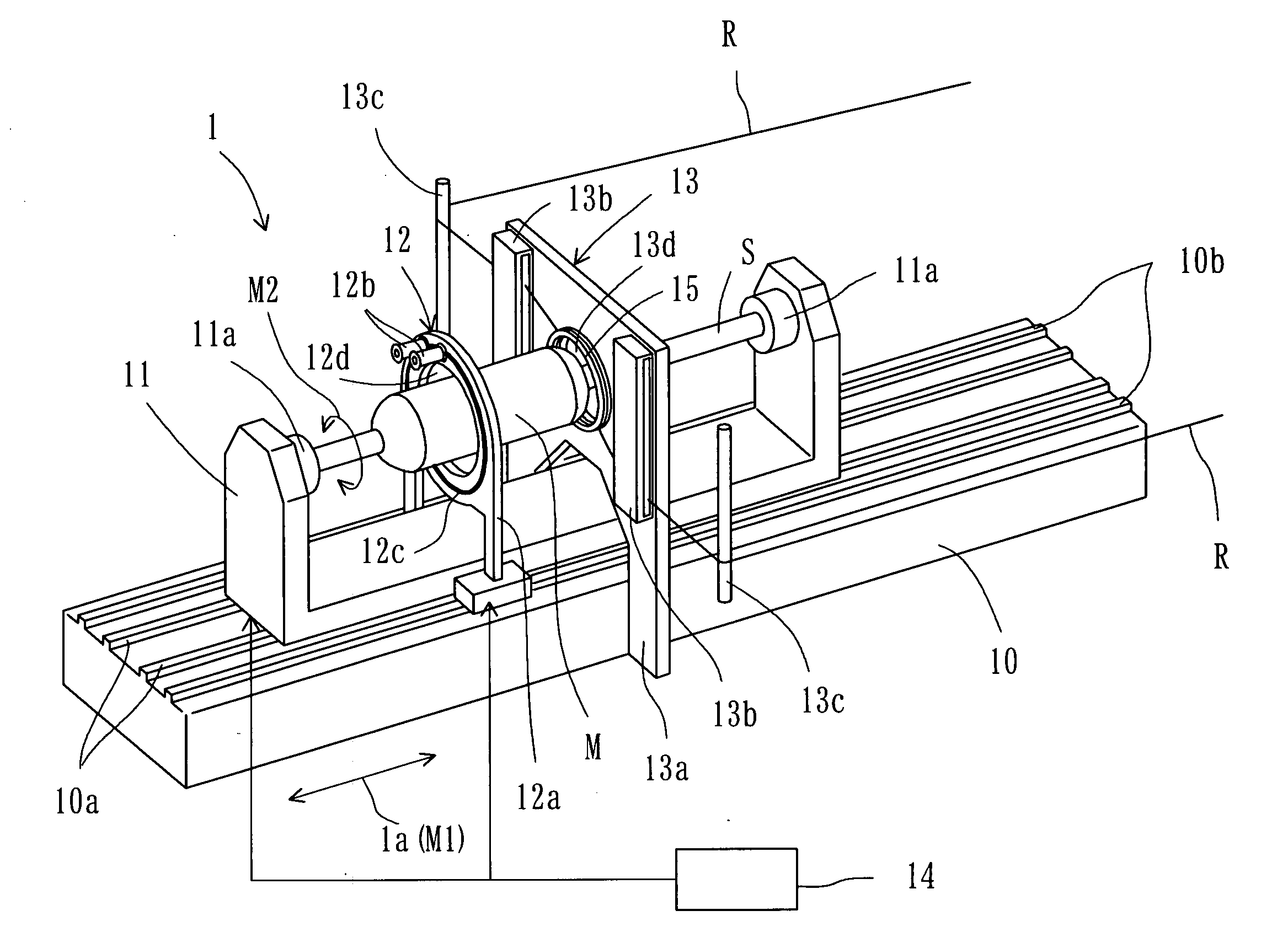
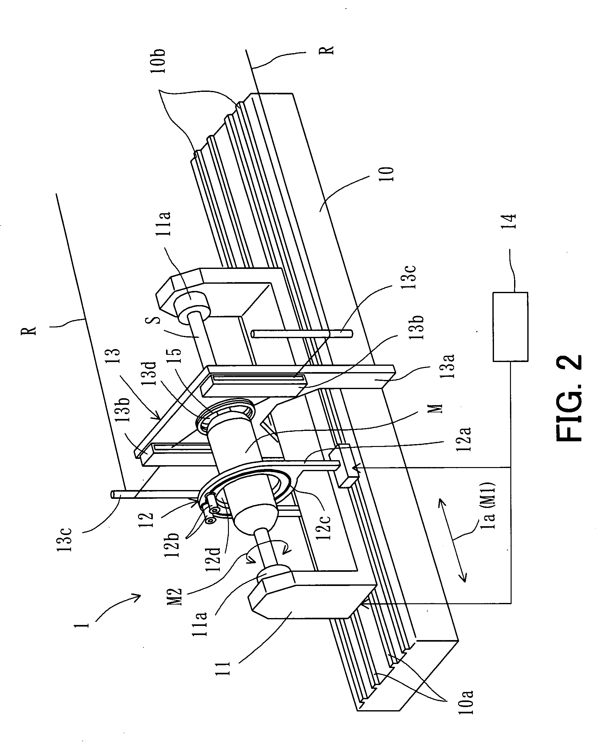
[0013]As described above, in the filament winding apparatus according to the present invention, the helical winding head includes the at least two guide arrays, each including a plurality of guide portions disposed along the circumferential direction of the mandrel, and the repositioning mechanism capable of repositioning the guide portions by rotating each guide array relative to another. Therefore, with the guide portions, a plurality of fiber bundles can be wound onto the mandrel at one time during the helical winding, thereby making it possible to shorten the manufacturing time. In addition, the repositioning mechanism simply repositions each guide array to a predetermined position, thereby making it possible to carry out the helical winding in a plurality of patterns at different angles. Thus, the helical winding can be readily carried out in a plurality of patterns, resulting in superior productivity.

Problems solved by technology

Conventionally, the filament winding apparatus winds a small number of fiber bundles onto the mandrel, and therefore when carrying out the helical winding in a plurality of patterns, product manufacturing takes a significant amount of time.
Although the manufacturing time can be shortened by winding wider fiber bundles onto the mandrel, the wider fiber bundles slip on a mirrored portion of the mandrel, resulting in a product of inferior quality.
Such filament winding apparatuses are capable of winding a layer of fiber bundles with a single winding operation, but they have difficulty in forming helical winding layers, such that fiber bundles in each layer are uniformly arranged in such a manner as to leave no space therebetween.

Method used


Image

  • Filament winding method and apparatus
  • Filament winding method and apparatus
  • Filament winding method and apparatus

Examples


Embodiment Construction

[0025]Hereinafter, a filament winding apparatus according to the present invention will be described in detail with reference to the accompanying drawings.

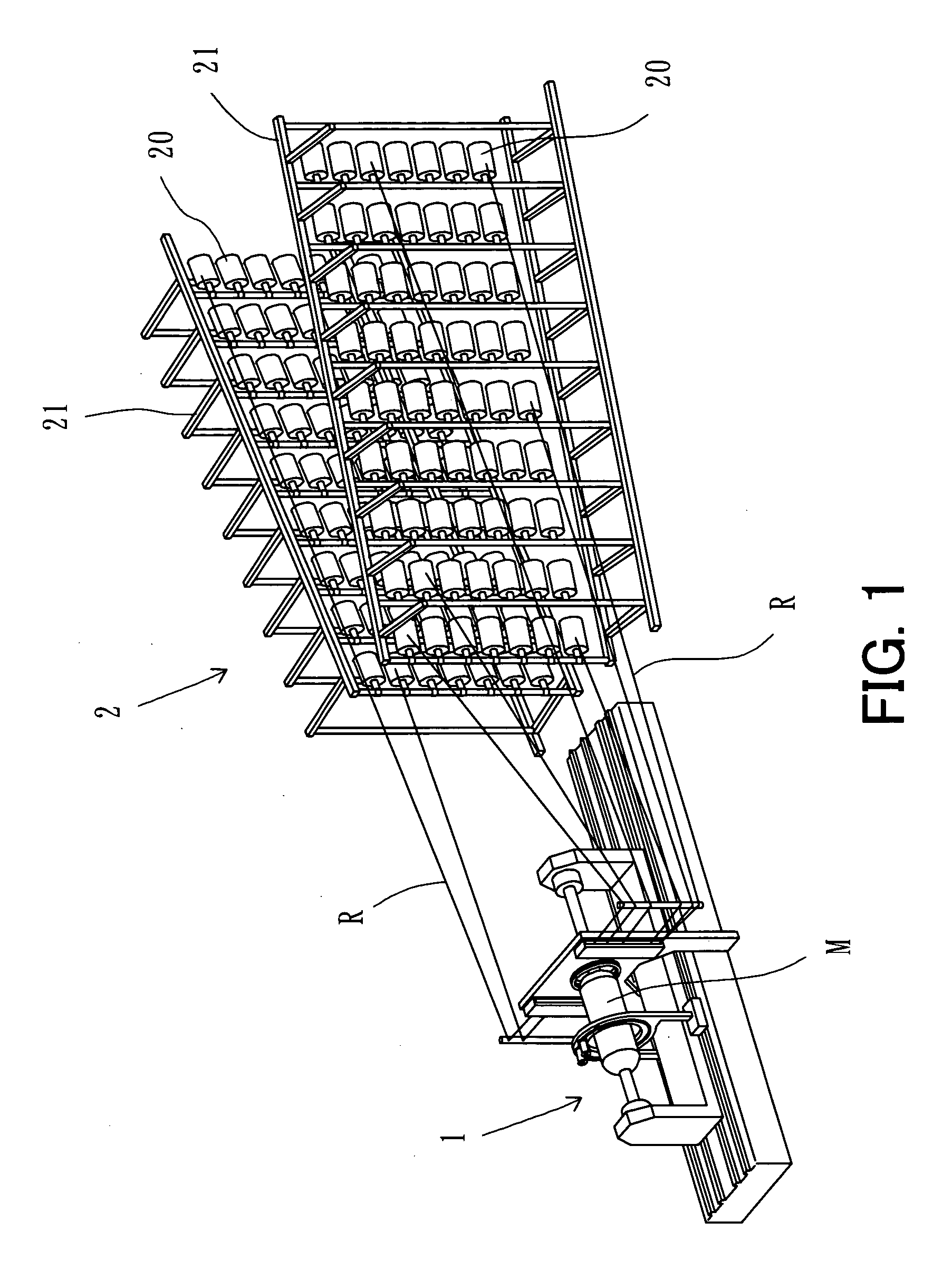
[0026]First, the structure of the filament winding apparatus will be described. FIG. 1 is a perspective view illustrating the filament winding apparatus. FIG. 2 is a perspective view illustrating a winder portion.

[0027]As shown in FIG. 1, the filament winding apparatus includes a winder portion 1, and a supplier portion 2. The winder portion 1 winds fiber bundles R onto a mandrel M. The supplier portion 2 includes creel supporters 21, each being provided with a plurality of creels 20. The creels 20 each hold a wound fiber bundle R.

[0028]The fiber bundles R are each made up of a fiber material consisting of, for example, a glass fiber and synthetic resin. The supplier portion 2 supplies the fiber bundle R unwound from each creel 20 to the winder portion 1.

[0029]The fiber bundles R have been previously impregnated with a thermosetti...


PUM


Abstract

Helical winding is reliably carried out in a plurality of patterns at different angles in a short period of time. A filament winding apparatus for winding fiber bundles onto the surface of a mandrel includes a helical winding head for use in helical winding of the fiber bundles onto the mandrel. The helical winding head includes at least two guide arrays, each including a plurality of guide portions disposed along a circumferential direction of the mandrel, and a repositioning mechanism capable of repositioning the guide portions by rotating each guide array relative to another.

Description

BACKGROUND OF THE INVENTION[0001]1. Field of the Invention[0002]The present invention relates to filament winding methods and apparatuses for winding fiber bundles onto the surface of a rotating mandrel, thereby manufacturing a pressure tank or suchlike.[0003]2. Description of the Background Art[0004]The filament winding apparatus is an apparatus for manufacturing hollow containers, such as pressure tanks, pipes, and the like. The filament winding apparatus winds fiber bundles onto a mandrel (a liner) to manufacture a product (a pressure tank or suchlike). The fiber bundle is made up of a fiber material consisting of, for example, a glass fiber and synthetic resin.[0005]In general, the filament winding apparatus manufactures a product by winding fiber bundles by means of both hoop winding ((a) of FIG. 3) and helical winding ((b) and (c) of FIG. 3), thereby making a plurality of layers (e.g., ten layers of more) of fiber bundles (see Japanese Laid-Open Patent Publication No. 10-11913...

Claims


Application Information

Patent Timeline
IPC IPC(8): B65H54/28
CPCB29C53/66B29C53/8016B29C53/665
Inventor UOZUMI, TADASHITAKASHIMA, HIROKITANIGAWA, MOTOHIRO
Owner MURATA MASCH LTD
Learn More