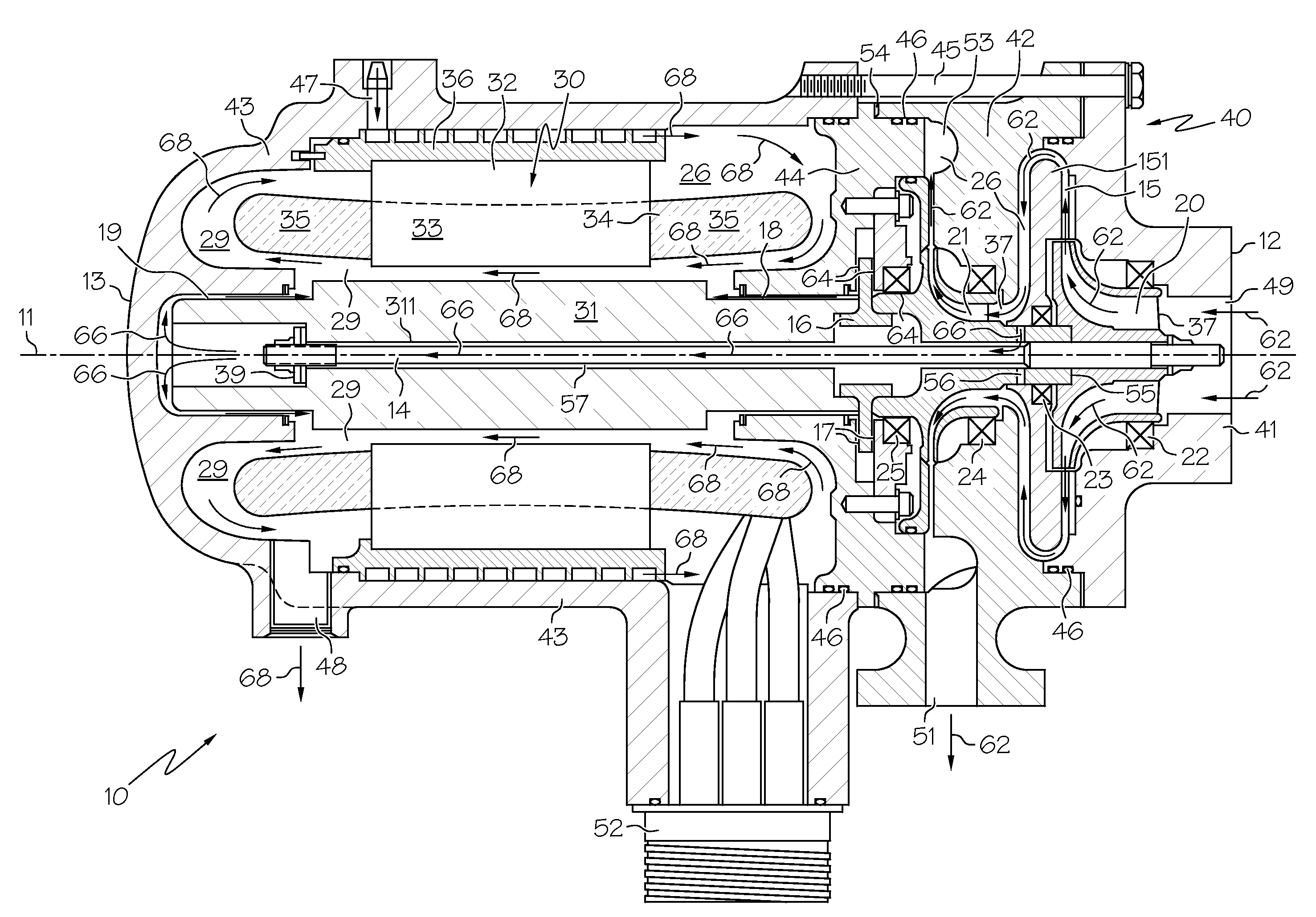
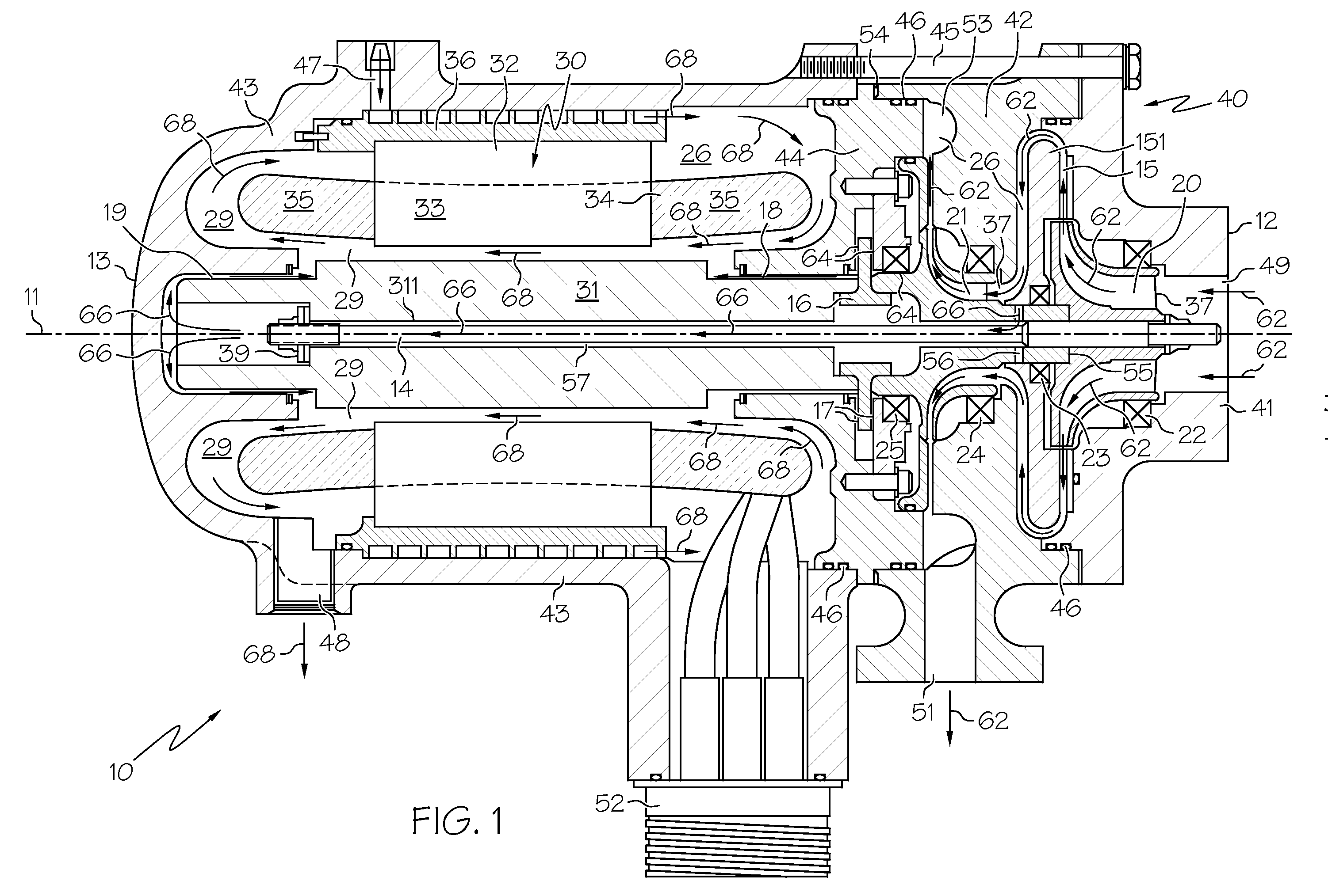
Two-stage vapor cycle compressor
- Summary
- Abstract
- Description
- Claims
- Application Information
AI Technical Summary
Problems solved by technology
Method used
Image

Examples
Embodiment Construction
[0015]The following detailed description is of the best currently contemplated modes of carrying out the invention. The description is not to be taken in a limiting sense, but is made merely for the purpose of illustrating the general principles of the invention, since the scope of the invention is best defined by the appended claims.
[0016]Broadly, the present invention provides a two-stage vapor cycle compressor and a method for vapor cooling an electrically driven two-stage vapor cycle compressor. In one embodiment the present invention provides a two-stage vapor cycle compressor that may be a relatively small and lightweight machine. The two-stage vapor cycle compressor as in one embodiment the present invention may be gravity insensitive, and may withstand the environmental conditions of aerospace applications. In one embodiment the present invention provides a two-stage cycle compressor that has a simple layout, that may be relatively easy to assemble, and that has relatively l...
PUM
 Abstract
Description
Claims
Application Information
 - R&D Engineer
- R&D Manager
- IP Professional
- Industry Leading Data Capabilities
- Powerful AI technology
- Patent DNA Extraction
Browse by: Latest US Patents, China's latest patents, Technical Efficacy Thesaurus, Application Domain, Technology Topic.
© 2024 PatSnap. All rights reserved.Legal|Privacy policy|Modern Slavery Act Transparency Statement|Sitemap