
Bioimpedance measurement system and method

a bioimpedance and measurement system technology, applied in the field of tissue treatment systems and methods, can solve the problems of lack of robustness, no method has proved entirely satisfactory, and the coolant may egress from the catheter

Inactive Publication Date: 2008-08-21
MEDTRONIC CRYOCATH LP
View PDF69 Cites 7 Cited by
  • Summary
  • Abstract
  • Description
  • Claims
  • Application Information

AI Technical Summary

Benefits of technology

The present invention provides methods and systems for detecting fluid egress, assessing lesion quality, determining tissue composition, and providing tissue contact assessment. These methods involve positioning a catheter at a tissue treatment site and measuring impedance voltage between electrodes while applying an electrical current. The measured impedance voltage is processed to determine if fluid egress is present, the quality of the lesion, the tissue composition, and the contact between the catheter and the tissue. The methods may be performed using a control unit, microprocessor, or impedance measuring device. The invention allows for improved detection and assessment of tissue quality and can help improve the accuracy of tissue treatment.

Problems solved by technology

However, none of these methods has proved entirely satisfactory.
The problem extends to all areas of tissue treatment wherein the tissue undergoes some change or “physiological event” during the course of treatment.
In addition to contact quality assessment, in treatment devices that employ fluid flows, detection and containment of leaks is a critical problem, especially in the operation of cryogenic devices for therapeutic purposes, lest a leak of coolant enter the body and thereby cause significant harm.
These techniques however, lack robustness, in that if the unitary balloon, cooling chamber, or other form of containment develops a crack, leak, rupture, or other critical structural integrity failure, coolant may egress from the catheter.

Method used


Image

  • Bioimpedance measurement system and method
  • Bioimpedance measurement system and method
  • Bioimpedance measurement system and method

Examples


Embodiment Construction

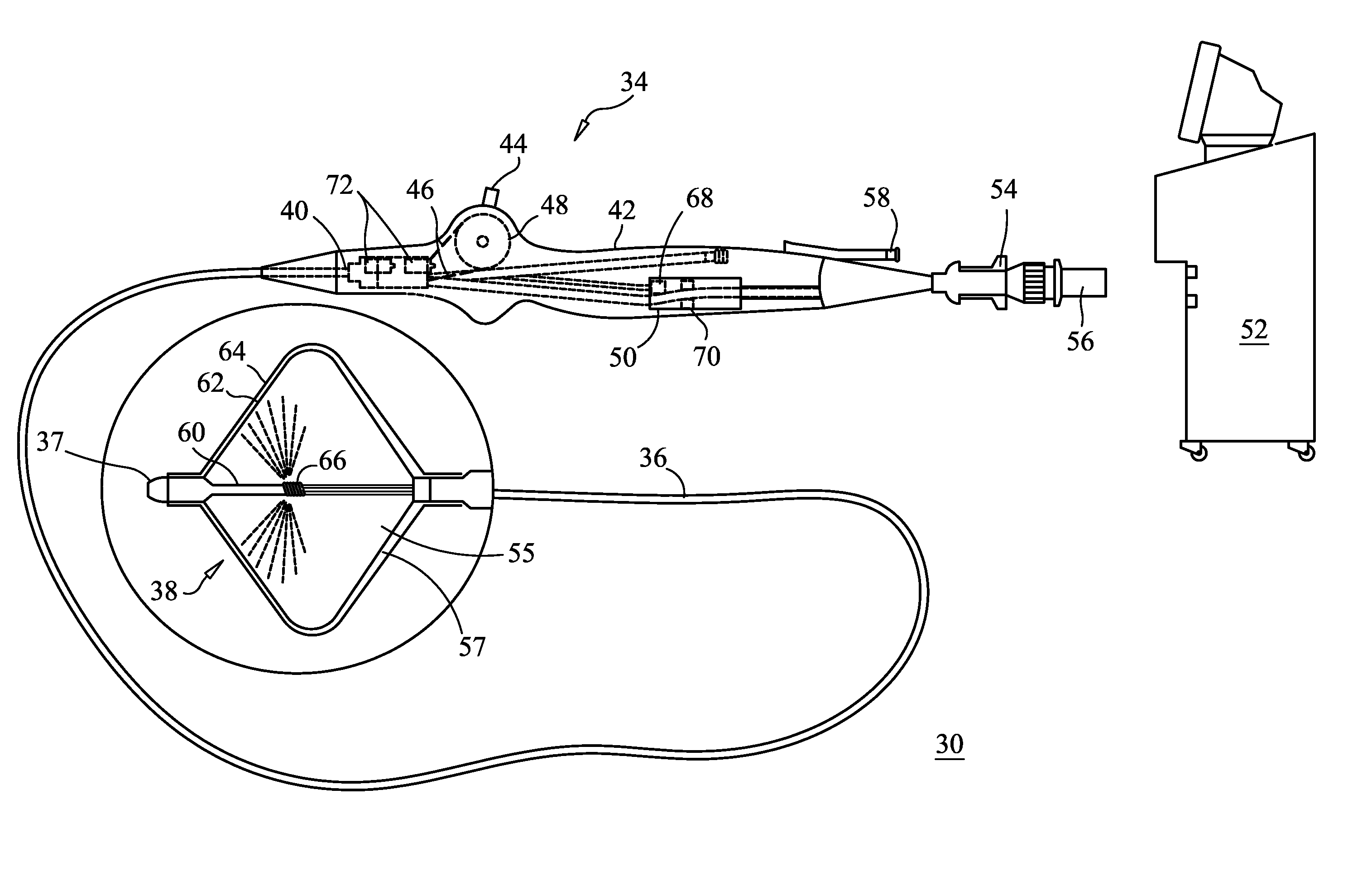
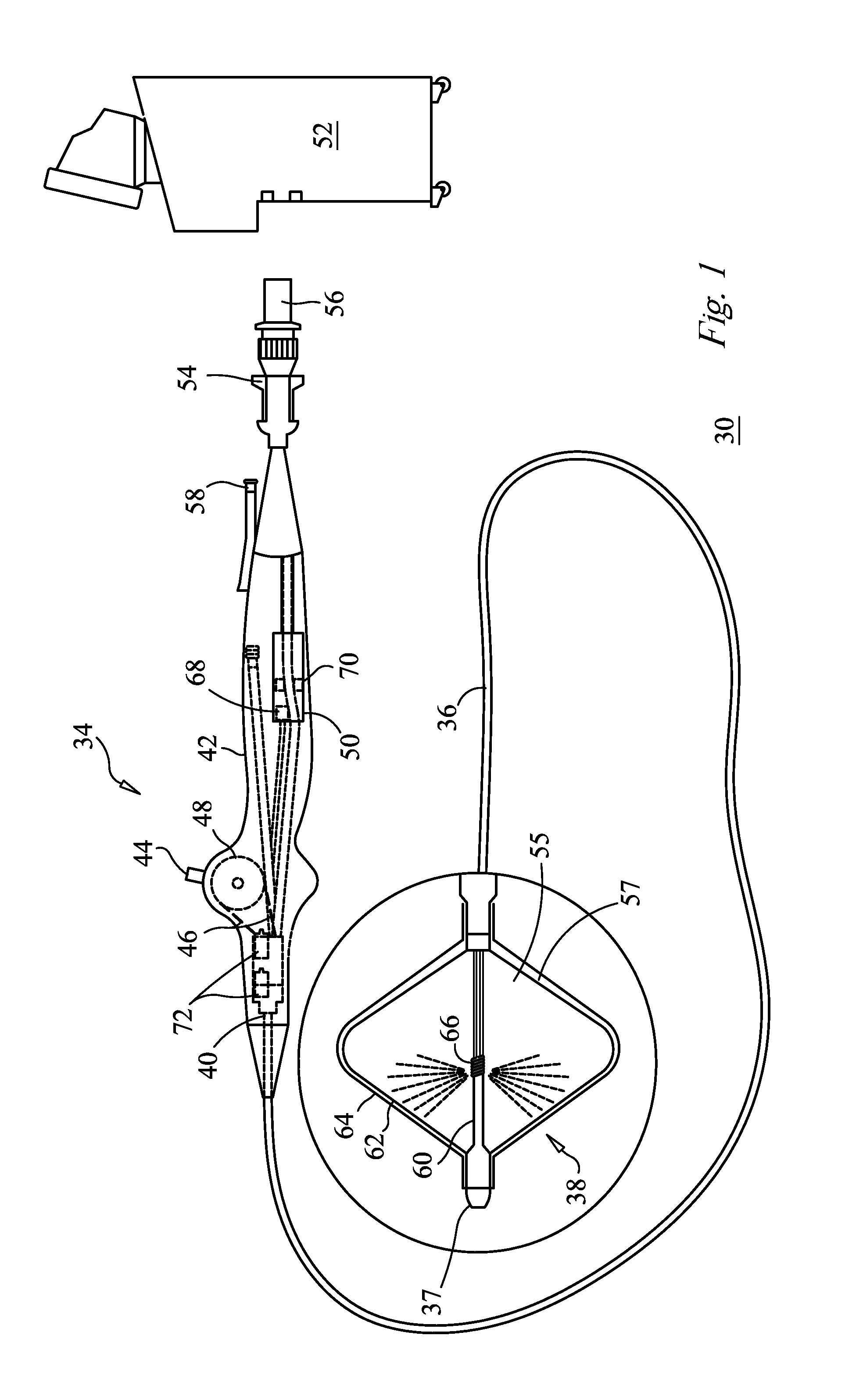
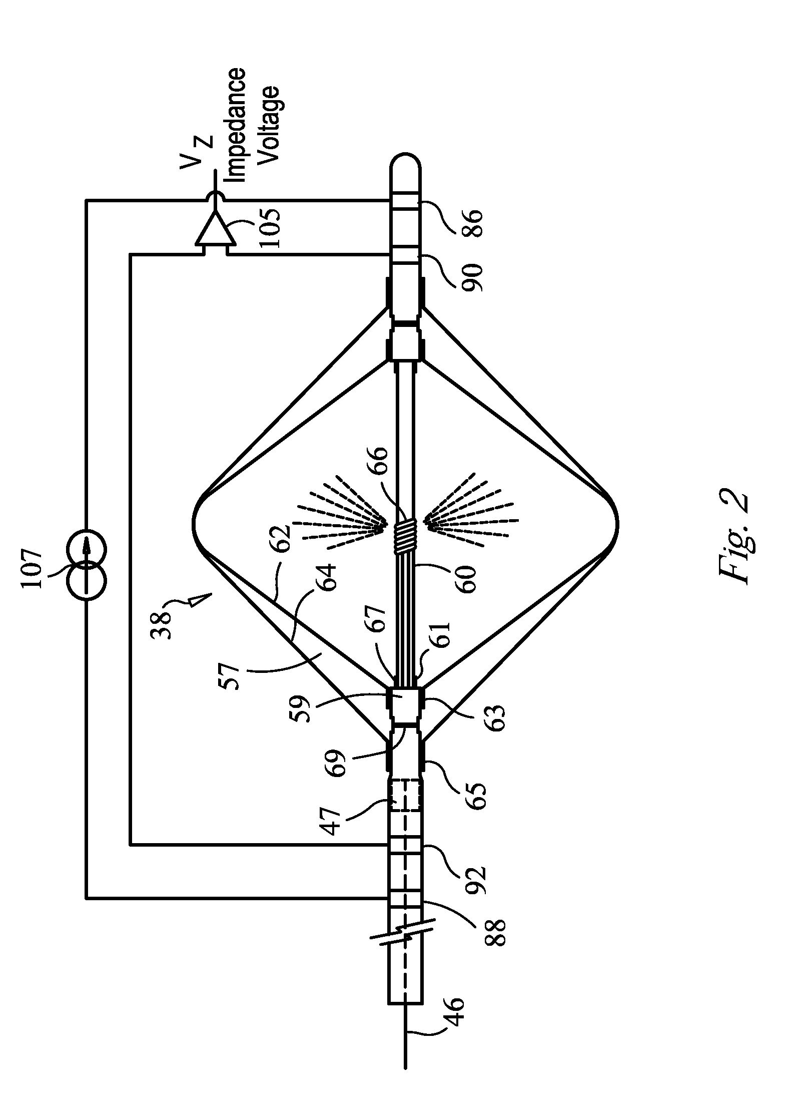
[0035]A system and method for detecting fluid egress including the steps of positioning a catheter at a tissue treatment site, where the catheter includes a shaft, which has a proximal end portion and a distal end portion, wherein the proximal end portion and the distal end portion define at least one fluid pathway therebetween, and the shaft has a treatment portion that includes at least four electrodes, a first pair of electrodes and a second pair of electrodes, applying an electrical current between the first pair of electrodes, measuring a impedance voltage between the second pair of electrodes, and processing the measured impedance voltage caused by the applied electrical current to determine if fluid egress is present.

[0036]The number and location of the electrodes will affect the system measurement sensitivity. For example, as the distance between the pair of measurement electrodes is decreased, the system measurement sensitivity is increased. On the other hand, as the distan...


PUM


Abstract

Methods and systems for detecting fluid egress, assessing lesion quality, determining tissue composition or structure, determining ice coverage of catheter tip and providing tissue contact assessment, by providing a catheter having a shaft with a proximal end portion and a distal end portion, the proximal end portion and the distal end portion define at least one fluid pathway therebetween with the shaft having a plurality of electrodes, positioning the catheter at a tissue treatment site, applying an electrical current between at least two of the plurality of electrodes, measuring impedance voltage between the at least two of the plurality of electrodes and, processing the measured impedance voltage caused by the applied electrical current to determine if fluid egress is present, to assess lesion quality, to determine tissue composition, ice cover of catheter tip, and to provide contact assessment. The system may have a control unit, a microprocessor, an impedance measuring device or the like to perform processing of impedance data.

Description

CROSS-REFERENCE TO RELATED APPLICATION[0001]This application is a Divisional of U.S. Utility patent application Ser. No. 11 / 283,057, filed Nov. 18, 2005, entitled BIOIMPEDANCE MEASUREMENT SYSTEM AND METHOD, the entirety of which is incorporated herein by reference.STATEMENT REGARDING FEDERALLY SPONSORED RESEARCH OR DEVELOPMENT[0002]n / aFIELD OF THE INVENTION[0003]The present invention relates to a system and method for treating tissue using cooled medical devices using electrical impedance measurements with the device.BACKGROUND OF THE INVENTION[0004]Effectiveness of cryotreatment of endocardial tissue is significantly affected by the contact of the catheter tip or thermally transmissive region to the tissue. Ex-vivo studies show a correlation between the lesion sizes created and the tip or thermally-transmissive region to tissue contact quality. A larger lesion size can be achieved with the same device by improving the tip to tissue pressure or contact. Various methods have been use...

Claims


Application Information

Patent Timeline
Patent Type & Authority Applications(United States)
IPC IPC(8): A61B5/053A61B18/02
CPCA61B5/0537A61B18/02A61B2018/0212A61B2018/0022A61B2017/00026
Inventor ABBOUD, MARWANAL ASMAR, JOHNNYHARMOUCHE, CHADI
Owner MEDTRONIC CRYOCATH LP
Learn More