Eureka AIR delivers breakthrough ideas for toughest innovation challenges, trusted by R&D personnel around the world.

Laser fiber holder

Inactive Publication Date: 2008-08-21
LAWLER DAVID E
View PDF28 Cites 0 Cited by
  • Summary
  • Abstract
  • Description
  • Claims
  • Application Information

AI Technical Summary

Benefits of technology

[0018]The present invention comprises a laser fiber holder for exposing a laser energy to living tissue. It includes a longitudinal sleeve defining a translucent distal end sleeve portion for encasing an extendible laser fiber tip spaced apart from an interior bore sidewall thereof and energizable for biostimulation treatment of tissue. A proximal sleeve portion having a proximal end including a small opening sized for cooperatively engaging the insulated exterior surface of the laser fiber in a friction fit holding the fiber within the sleeve at a desired length and holding the tip at a set distance from the tissue providing the laser energy at a selected point above the tissue and protecting the eyes of the user from direct laser light.
[0020]It is an object of the present invention to provide a laser fiber holder which eases the proper placement and delivery of the laser energy exposed to living tissue during medical procedures. The device allows for easy positioning of the fiber and thus the fiber tip remains at a fixed distance from the end of the tool.
[0021]Another object of the present invention is to provide a laser handpiece which eliminates the eye discomfort caused to the user by the bright red aiming light while still providing visual feedback to indicate the laser energy delivery site.
[0022]Another object of the present invention is to provide a laser handpiece which enables the user to use the device for long periods of time without the discomfort caused by a hot handle.
[0027]The laser fiber enters the handpiece proximally and it's position is easily maintained by friction rather than being fixed by a conventional gripping device as shown in the prior art drawing of FIG. 6. The DELRIN sleeve prevents eye irritation to the user caused by the bright red laser aiming beam and yet allows enough light to come through to see the location of the fiber's tip. Additionally, the DELRIN prevents heat build-up from the burning of tissue over a long period of time.

Problems solved by technology

Three problems are inherent in typical devices used today:A.
After continued use, the handpiece can become uncomfortably hot.

Method used


Image

  • Laser fiber holder
  • Laser fiber holder
  • Laser fiber holder

Examples


Embodiment Construction

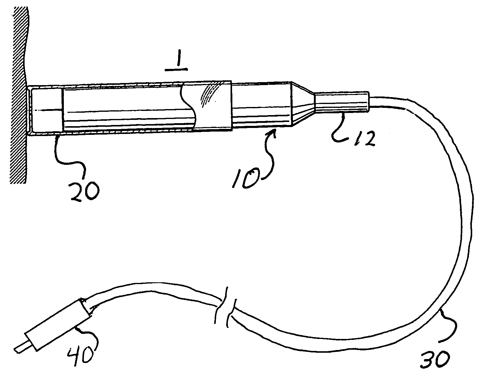
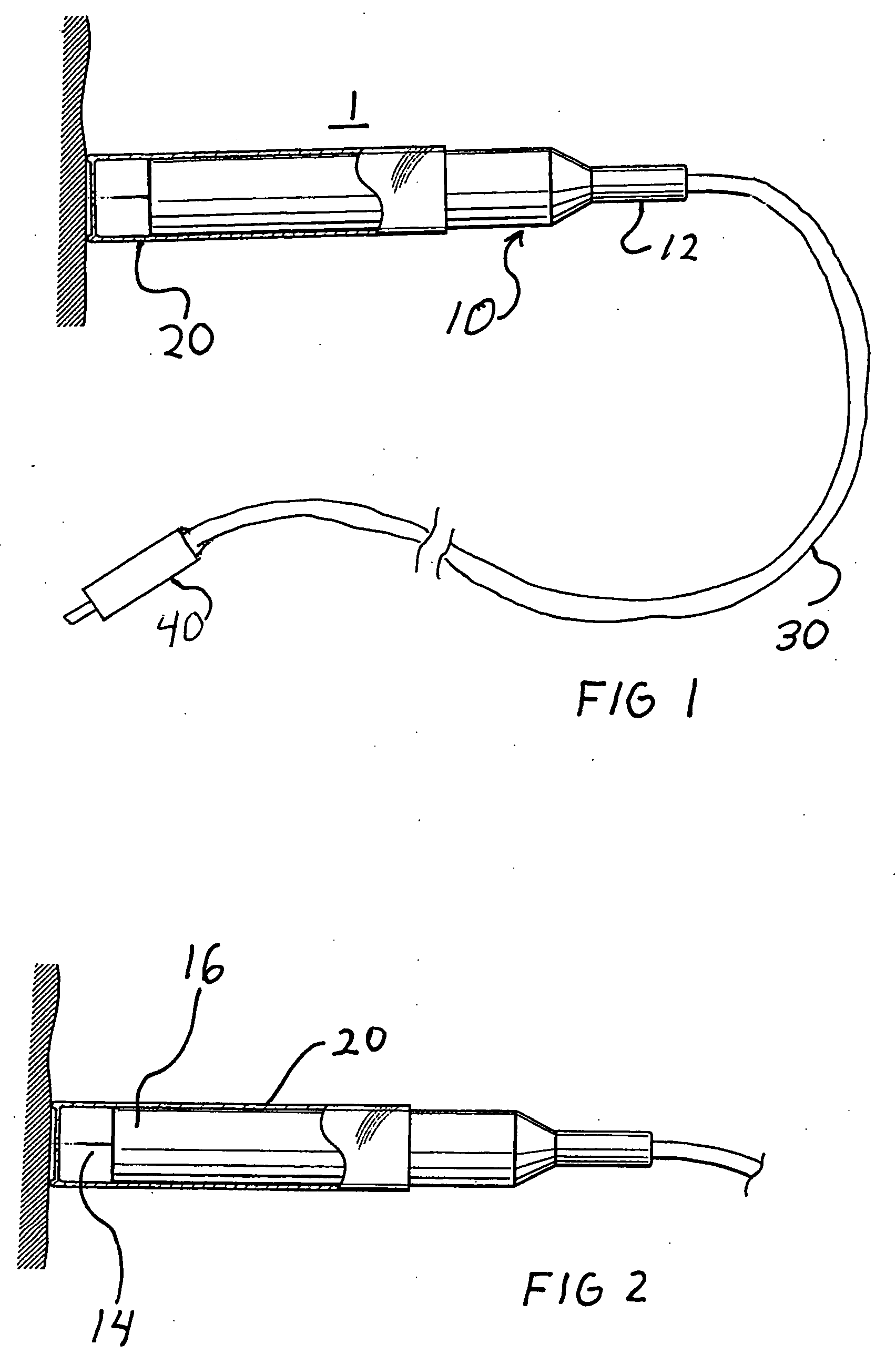
[0028]Referring to FIG. 1, a laser fiber handpiece is pictured comprising an optical fiber encased within an optical fiber sheath (30) and a handpiece (1) comprising a longitudinal sleeve (10) proximally holding the fiber sheath (30) and a second longitudinal sleeve (20) distally exposing the fiber tip and mechanically fixed onto the first longitudinal sleeve (10). The proximal end (12) of the longitudinal sleeve (10) is externally tapered. The entire metal sleeve (10) including proximal end (12) is drilled to a diameter which gives a friction fit to the optical fiber sheath.

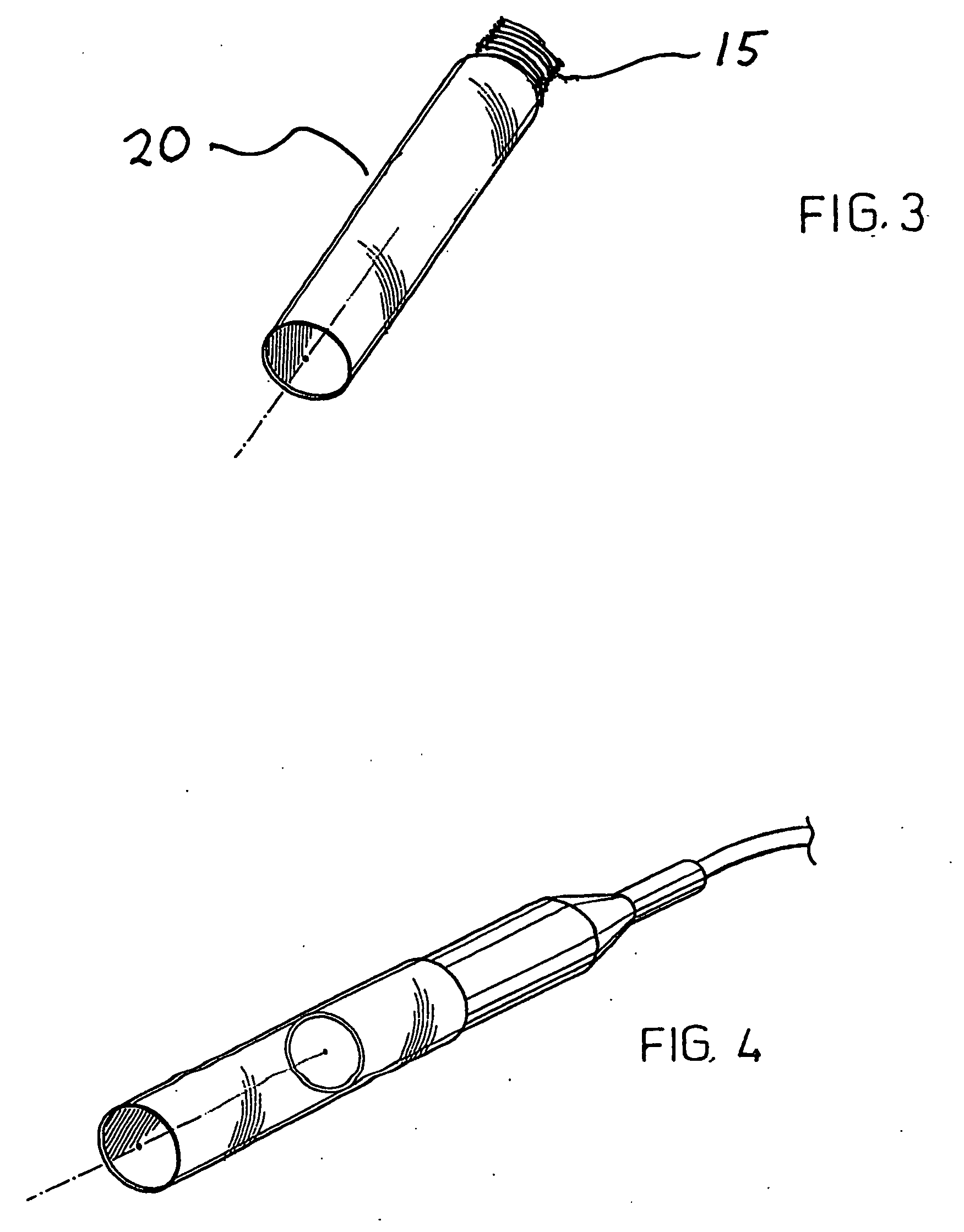
[0029]FIG. 3 illustrates the two sleeves, a metallic sleeve (10) and a DELRIN sleeve (20) separated,. The male threads (15) of the DELRIN sleeve are shown. The proximal sleeve (10) has the corresponding female threads (not shown). The two are connected together to form the combined handpiece.

[0030]FIG. 2 again shows the two sleeves (10) and (20) as separate members with the female threads (16) of the sleeve (10)...


PUM


Abstract

A laser fiber holder for exposing laser energy to living tissue, comprising a longitudinal sleeve having a translucent distal end section for encasing an extendible laser fiber tip energizable for exposing laser energy to living tissue and a proximal end having a smaller opening for cooperatively engaging the laser fiber in a friction fit holding the fiber within the sleeve at a desired length and holding the tip at a set distance invention the tissue providing laser energy at selected point above the tissue and protecting the eyes of the user from direct laser light.

Description

[0001]This application claims priority from U.S. Provisional application Ser. No. 60 / 859,321 filed Nov. 16, 2006.FIELD OF INVENTION[0002]The present invention relates to devices for treating periodontal disease and skin maladies, blemishes or discolorations, particularly to devices which incorporate laser energy shown on the affected area and used to either stimulate tissue healing or growth or to kill bacteria or debride diseased tissue.BACKGROUND OF THE INVENTION[0003]The use of laser light for treatment of various skin or periodontal issues has been common for years. The laser beam is exposed to the skin, tissue, or a die applied to the skin or tissue to concentrate the energy at the desired target. The target is then heated by the laser energy and the desired effect is accomplished. The laser is aimed at the target by holding a handpiece containing optical fibers which transmit the laser beam to the target. The beam is emitted from the end of the handpiece and can thus be aimed ...

Claims


Application Information

Patent Timeline
IPC IPC(8): A61B18/22
CPCA61N2005/0644A61N5/0613
Inventor LAWLER, DAVID E.
Owner LAWLER DAVID E
Why Eureka
Eureka Blog
Learn More