
Simulator For Use With a Breathing-Assist Device

Inactive Publication Date: 2008-08-21
MAQUET CRITICAL CARE
View PDF10 Cites 11 Cited by
  • Summary
  • Abstract
  • Description
  • Claims
  • Application Information

AI Technical Summary

Benefits of technology

[0025]Using a signal having well defined properties (frequency spectrum, amplitude) is advantageous in testing since it is easy to predict what the response on each channel should be. Thus, each channel can be tested separately in a reliable manner.
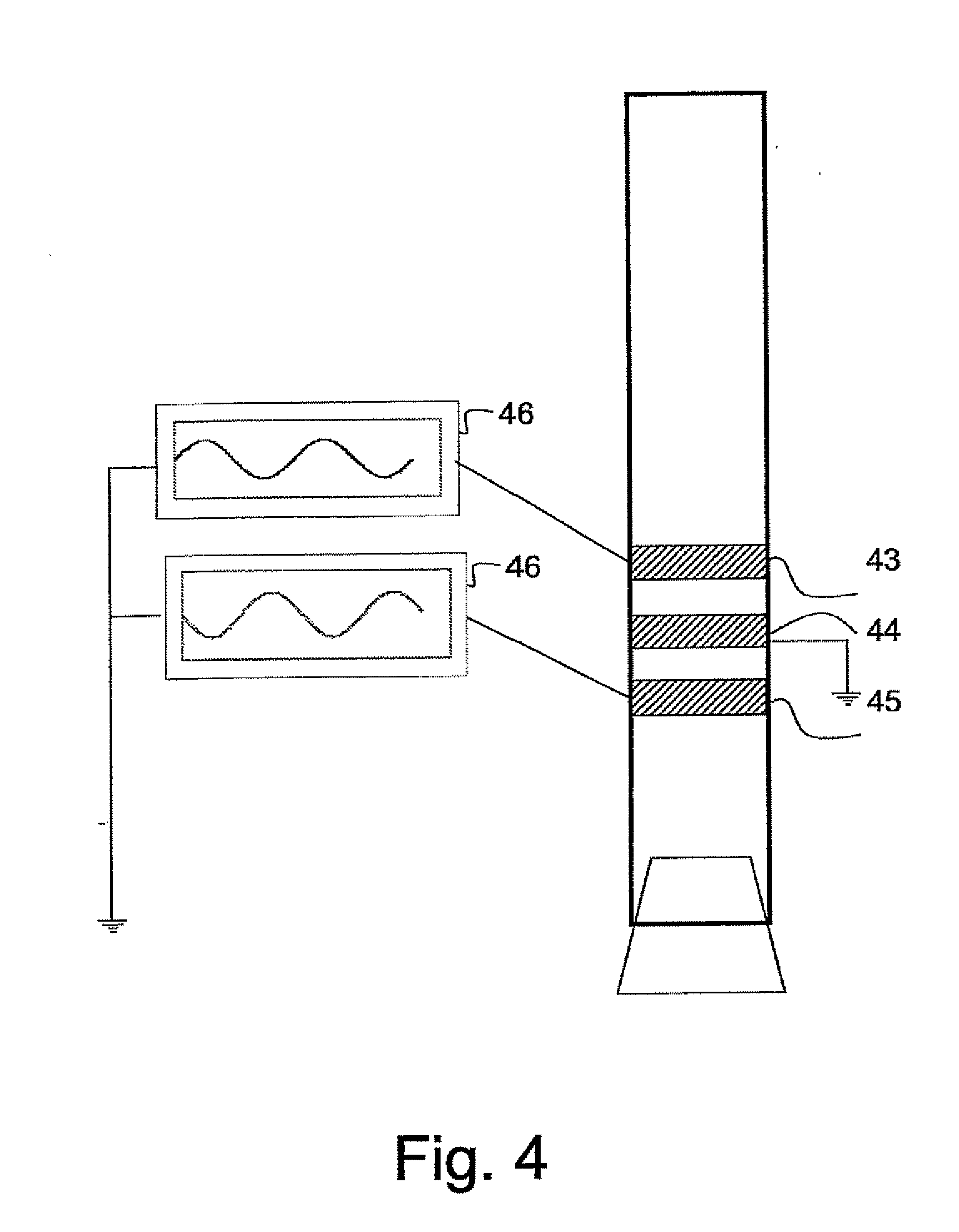
[0033]This embodiment also makes it possible to test the catheter and its connection to the ventilator. The catheter can be connected to the simulating device and a test program may be run to ensure that all electrodes are working and that there are no short circuits or other defects.

Problems solved by technology

The pressure or air flow must be measured continuously and it may be difficult to determine which part of the signal originates from the patient.
EP 1 205 202 discloses an EMG controlled ventilator system, but said system does not propose a way of ensuring that the units providing the EMG control of the ventilator actually work and provide correct signals.
The new technology of EMG, or other bioelectric signal, controlled ventilation provides a powerful tool for physicians and medical personal working with patients in need of ventilation support, however it also causes new problems and challenges.

Method used


Image

  • Simulator For Use With a Breathing-Assist Device
  • Simulator For Use With a Breathing-Assist Device
  • Simulator For Use With a Breathing-Assist Device

Examples


first embodiment

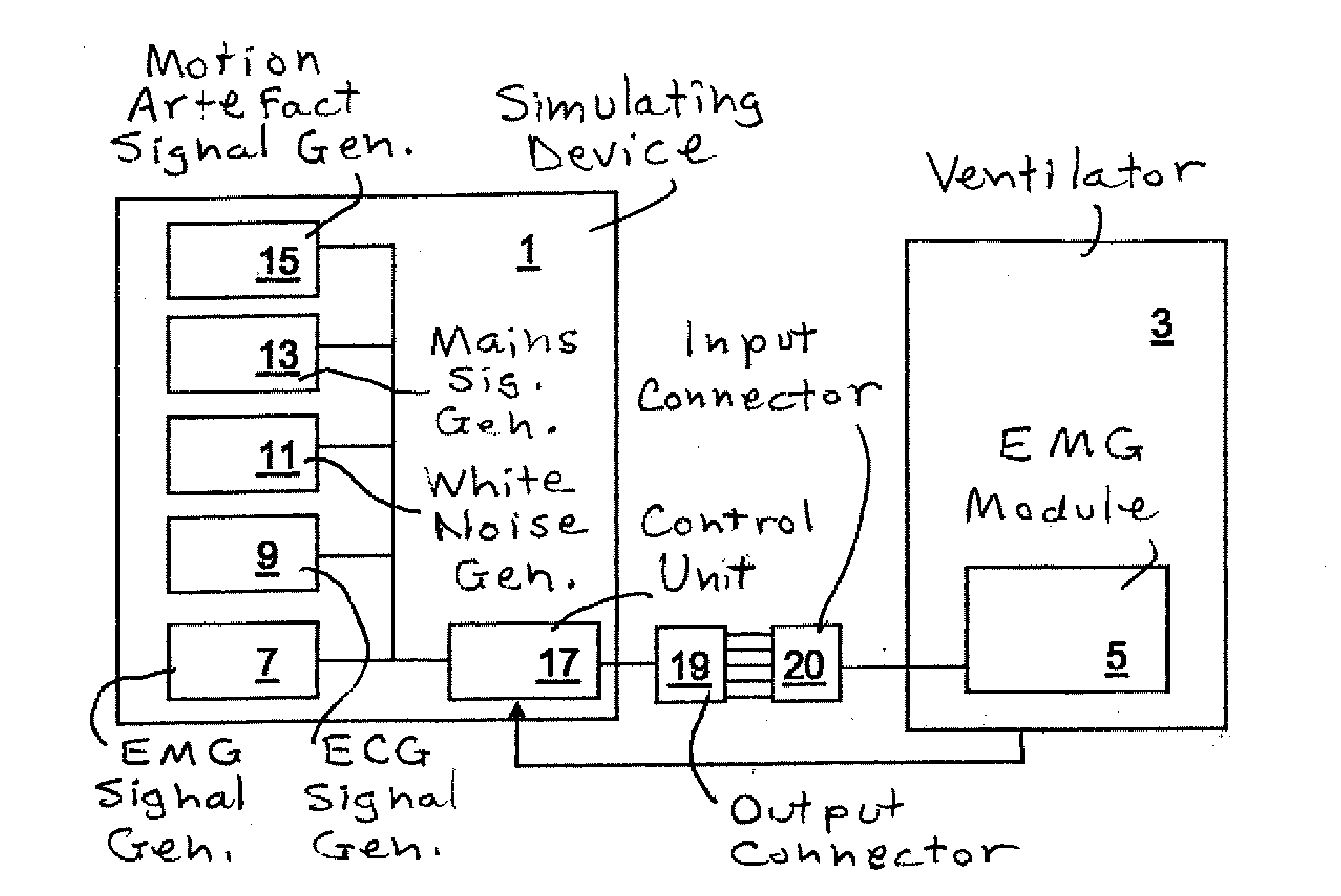
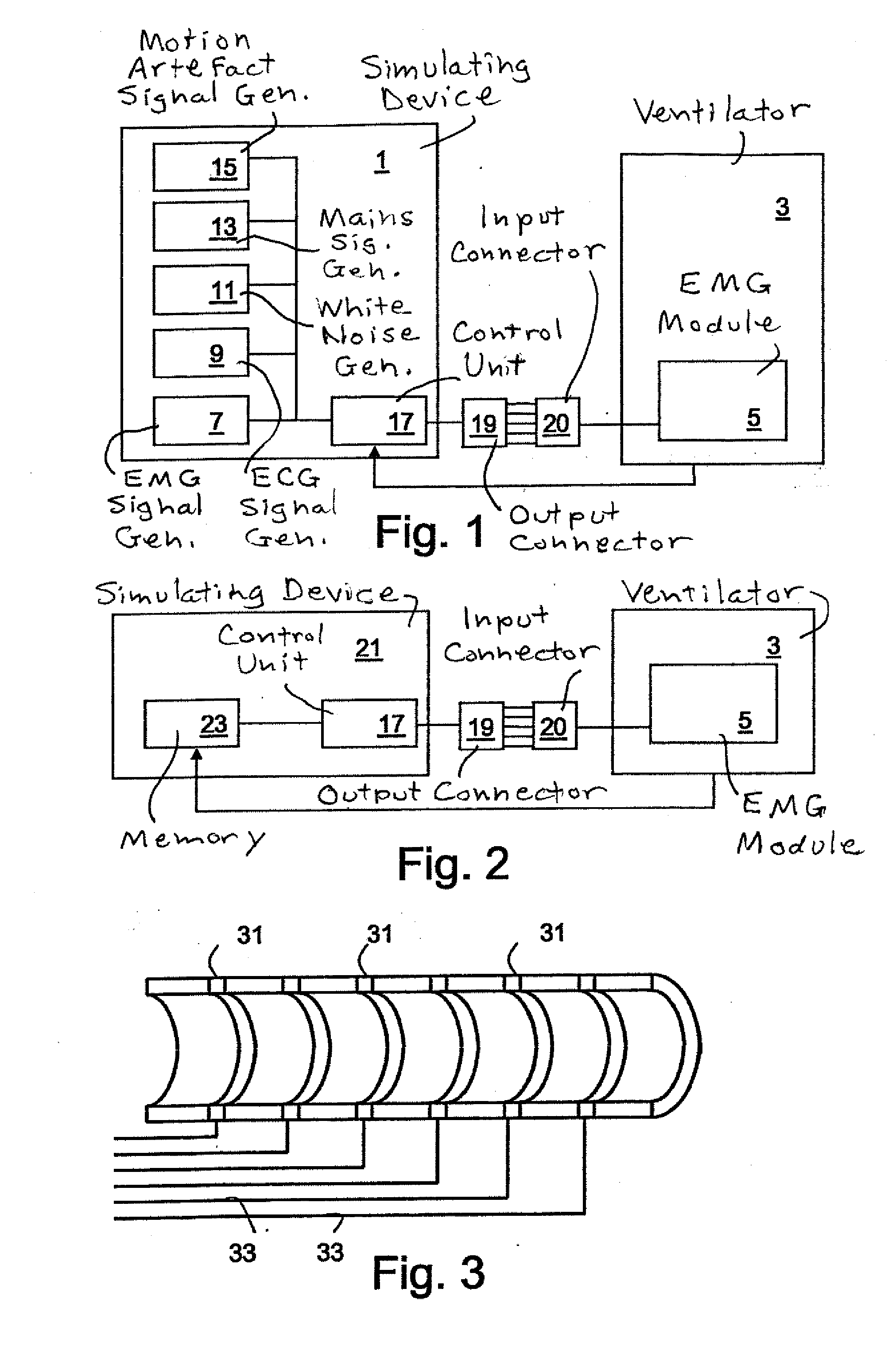
[0042]FIG. 1 illustrates a simulating device 1 according to the invention. The simulating device 1 is connectable to a ventilator 3 for providing a simulated EMG signal to an EMG module 5 in the ventilator 3.

[0043]The simulating device 1 has an EMG signal generator 7 arranged to generate a simulated EMG signal. Instead of the EMG signal another signal indicating the patient's breathing may be used, such as the phrenic nerve signal of the patient. Preferably, the simulating device 1 also has an ECG signal generator 9 arranged to generate a simulated ECG signal that can be combined with the simulated EMG signal in order to simulate ECG interference which normally occurs in EMG signals.

[0044]The simulating device 1 may also has other signal generators 11, 13, 15 for simulating other disturbances to the EMG signal. Hence, the figure shows a white noise generator 11, to simulate the background noise, a mains signal generator 13 to simulate the 50 Hz or 60 Hz disturbances caused by the ma...

second embodiment

[0056]FIG. 2 illustrates a simulating device 21 according to the invention. As before, a ventilator 3 has an EMG module 5 arranged to receive an EMG signal through an input connector 20. Instead of the signal generator 7 in FIG. 1, the simulated EMG signal in this embodiment is an EMG signal recorded from an actual patient and stored in a memory 23. This EMG signal will already comprise the disturbances normally found in an EMG signal, such as an ECG signal and other signals mentioned above. Therefore, there is no need for a separate ECG signal generator. The simulated compound EMG signal is provided to the output connector 19, preferably through a control unit 17 arranged to control the amplitude of the signal.

[0057]The simulator 21 shown in FIG. 2 can also be arranged to receive a feedback signal from the ventilator, in a similar way to the simulator 1 of FIG. 1. In this case the feedback signal can be provided to the control unit 17

[0058]Of course, the two embodiments shown in FI...


PUM


Abstract

Function testing of a ventilator using an EMG or other bioelectric signal representative of the breathing of the patient to control ventilation is enabled by a simulating device for use with a breathing related device for monitoring and / or controlling a patient's breathing, the simulating device including a signal generator for providing a simulated bioelectric compound signal related to the patient's breathing function, and a contact for outputting the simulated bioelectric compound signal. The simulating device can also be used for training purposes and in the development of new ventilators.

Description

BACKGROUND OF THE INVENTION[0001]1. Field of the Invention[0002]The present invention concerns a simulator that is suitable for use with a breathing-assist apparatus that monitors and / or controls the breathing of a patient.[0003]2. Description of the Prior Art[0004]The present invention relates to a simulating device as defined in the preamble of claim 1, a method as defined in the preamble of claim 13 and a computer program product as defined in the preamble of claim 24.[0005]Ventilators are commonly used to provide assisted breathing to patients. The breathing support provided by a ventilator may be controlled in different ways to ensure appropriate ventilation of the patient. Traditionally the breathing support is based on measurements on the patient's ventilation, that is, air pressure and / or air flow in the patient's lungs, and the support is triggered by detection of the inspiratory efforts of the patient. The pressure or air flow must be measured continuously and it may be di...

Claims


Application Information

Patent Timeline
IPC IPC(8): A61N1/00
CPCA61B5/0488A61B5/08A61M16/00G09B23/288A61M2230/08A61N1/08A61M2209/02A61M16/024A61B5/389
Inventor BLOMBERG, URBANJALDE, FREDRIK
Owner MAQUET CRITICAL CARE
Learn More