Method and apparatus for controlling a homogeneous charge compression ignition engine

a technology of compression ignition and homogeneous charge, which is applied in the direction of electric control, machines/engines, output power, etc., can solve the problems of affecting the phasing control of combustion using internal egr, affecting the output of the engine, and affecting the phasing control of the engin

Active Publication Date: 2008-08-28
GM GLOBAL TECH OPERATIONS LLC
View PDF8 Cites 26 Cited by
  • Summary
  • Abstract
  • Description
  • Claims
  • Application Information

AI Technical Summary

Problems solved by technology

One of the major concerns in an application of an HCCI engine is that auto-ignited combustion is vulnerable to variations in fuel octane levels and variations in environmental conditions including ambient temperature and humidity.
This is because such variations can change the cylinder charge conditions and, as a result, significantly affect the ignition timing of auto-ignited combustion, and may induce unwanted vibrations in engine output.
Thus, combustion phasing control using internal EGR is typically limited to operating conditions whereat the combustion phasing changes monotonically with internal EGR.
Without precise information about environmental and fuel quality changes, it is challenging to identify changes in operating conditions in real time.

Method used


Image

  • Method and apparatus for controlling a homogeneous charge compression ignition engine
  • Method and apparatus for controlling a homogeneous charge compression ignition engine
  • Method and apparatus for controlling a homogeneous charge compression ignition engine

Examples


first embodiment

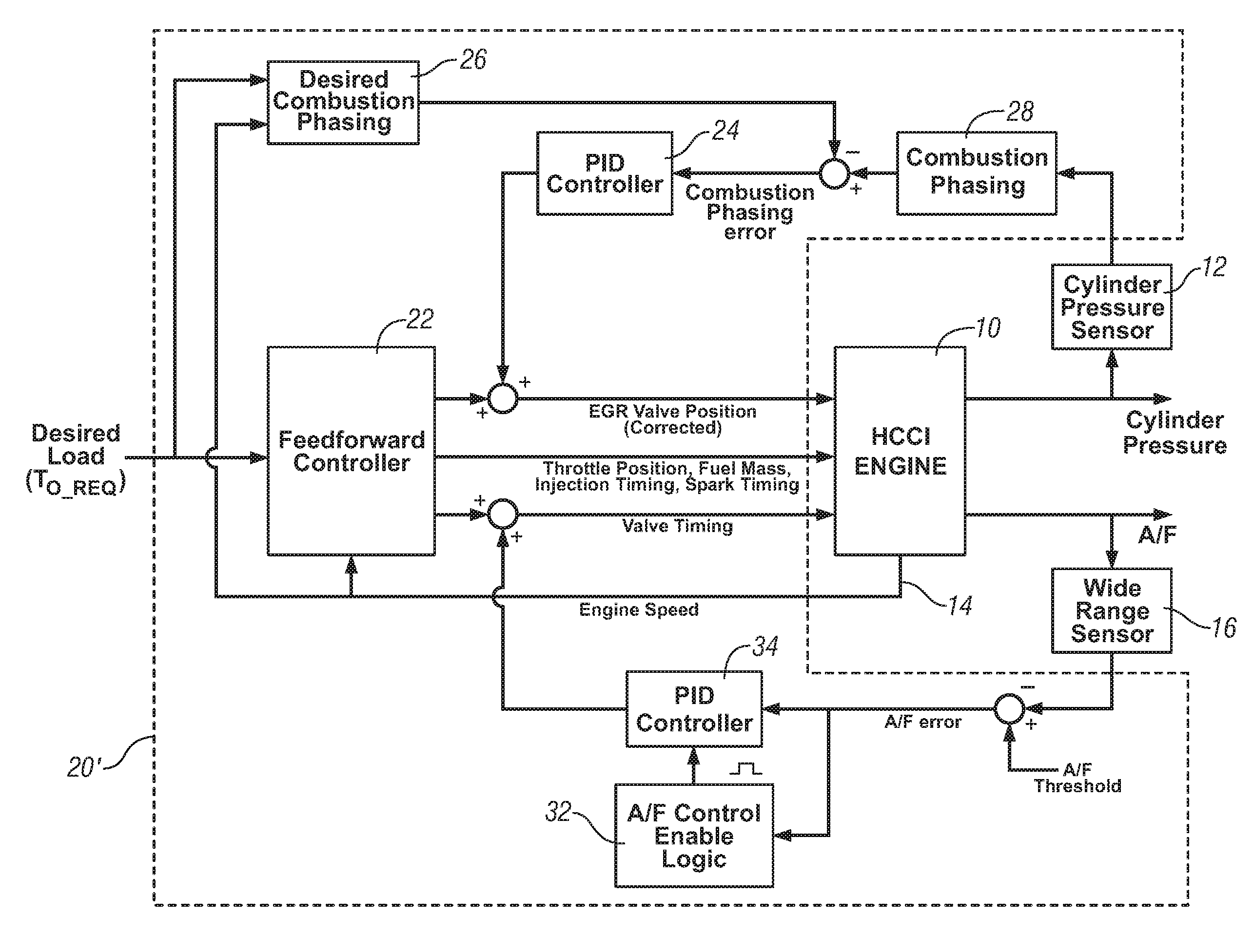
[0020]Referring again to FIG. 4, the control scheme is depicted. Operation of the exemplary HCCI engine 10 is controlled by controlling actuators, including EGR valve position, throttle position, fuel mass and injection timing, spark ignition timing and control, intake and exhaust valve timing and phasing control. Monitored engine outputs comprise engine speed 14 (in RPM) and combustion phasing, shown herein in the form of cylinder pressure 11 measured using the cylinder pressure sensor 12, and various other sensed or estimated outputs necessary for ongoing operation and control. The control scheme, executed in the control module 20, monitors the engine speed, and the operator request for torque (TO—REQ), or desired load. The control scheme includes a feedforward controller 22 and a PID controller 24. The feedforward controller 22 is preferably executed utilizing information from predetermined calibrations to achieve a successful HCCI combustion under steady state operating conditio...

second embodiment

[0023]Referring again to FIG. 6, the control scheme is depicted, comprising combining the combustion phasing control an air-fuel ratio controller to control the air-fuel ratio to be above a certain threshold using by control of valve timing and phasing using valve control actuators. Thus, specific engine designs that are more sensitive to changes in ambient environment and / or fuel octane can control engine operation using the external EGR and valve train control to control air-fuel ratio and compensate any combustion phasing errors. In this embodiment, the exemplary HCCI engine 10 has control inputs including EGR valve position, throttle position fuel mass and injection timing, spark ignition timing and control, and intake and exhaust valve control capability. Monitored engine outputs comprise engine speed (in RPM) 14 and combustion phasing, shown herein in the form of measured cylinder pressure 11, and air / fuel ratio, shown herein monitored by an air / fuel ratio sensor 16. The contr...


PUM


Abstract

The invention comprises a method for controlling operation of a homogeneous charge combustion ignition engine operating in an auto-ignition mode. The method comprises determining a desired combustion phasing; and, controlling a mass flowrate of externally recirculated exhaust gas based upon an actual combustion phasing. A closed-loop control scheme is executed to control the mass flowrate of externally recirculated exhaust gas based upon a difference between the actual and the desired combustion phasing.

Description

TECHNICAL FIELD[0001]This invention relates to operation and control of homogeneous-charge compression-ignition (HCCI) engines.BACKGROUND OF THE INVENTION[0002]The statements in this section merely provide background information related to the present disclosure and may not constitute prior art.[0003]In an HCCI (Homogeneous Charge Compression Ignition) engine, combustion is flameless, and occurs spontaneously occurs throughout the entire combustion chamber volume. The homogeneously mixed cylinder charge is auto-ignited as the cylinder charge is compressed and its temperature increases. The ignition timing of auto-ignited combustion depends on initial cylinder charge conditions including primarily temperature, pressure, and composition. Thus, it is important to coordinate engine control inputs, such as fuel mass, injection timing, and intake and exhaust valve motion, to ensure robust HCCI combustion. Depending on the motion of the intake and exhaust valves, there are two primary oper...

Claims


Application Information

Patent Timeline
Patent Type & Authority Applications(United States)
IPC IPC(8): F02M7/00
CPCF02B1/12Y02T10/47F02D35/023F02D35/028F02D41/0052F02D41/006F02D41/0065F02D41/1401F02D41/1454F02D41/3035F02D2041/001F02D2041/1409F02D2041/141F02D2041/1418F02M25/0752F02M25/0756Y02T10/128F02D13/0219F02M26/48F02M26/01Y02T10/12Y02T10/40
Inventor KANG, JUN-MOCHANG, CHEN-FANGCHANG, MAN-FENGWERMUTH, NICOLE
Owner GM GLOBAL TECH OPERATIONS LLC
Why Eureka
Try Eureka