
Electromagnetic Radiation Collector

a technology of electromagnetic radiation and collector, which is applied in the field of electromagnetic radiation collection, can solve the problems of high capital cost of conventional devices for collecting radiant energy to generate energy in a useful form, and inability to generate high enough temperatures to be useful for many applications, and achieves the effects of low cost, light and inexpensive, and large area

Inactive Publication Date: 2008-08-28
SUNDAY SOLAR TECH
View PDF26 Cites 10 Cited by
  • Summary
  • Abstract
  • Description
  • Claims
  • Application Information

AI Technical Summary

Benefits of technology

[0005]The invention seeks to overcome at least some of the deficiencies in the prior art by providing an EM radiation collection and concentration device which can cover a large area, have a low profile, have no requirement to track the source and be constructed so as to be relatively light and inexpensive.
[0006]There is a pressing need to be able to generate energy from renewable energy sources. Solar energy is one such resource which has potential to be exploited. Conventional devices for collecting radiant energy to generate energy in a useful form suffer from a high capital cost and / or the inability to generate high enough temperatures to be useful for many applications. The invention seeks to overcome these deficiencies in the prior art by providing a radiant energy concentration device that can gather energy from a relatively large area and concentrate it onto a small target area. The device is relatively inexpensive to produce, can be light in construction and has the potential to generate high target temperatures or, in the case of conversion to electricity by photovoltaic cells, require only a small area of cells, thus saving cost.
[0007]The invention is directed to a device that can cover relatively large collections areas at relatively low cost, does not necessarily require materials of particular refractive index, can be made of light construction and can concentrate the radiation onto a single target area.

Problems solved by technology

Conventional devices for collecting radiant energy to generate energy in a useful form suffer from a high capital cost and / or the inability to generate high enough temperatures to be useful for many applications.

Method used


Image

  • Electromagnetic Radiation Collector
  • Electromagnetic Radiation Collector
  • Electromagnetic Radiation Collector

Examples


Embodiment Construction

[0021]An exemplary embodiment of the invention is shown in the drawings and described herein.

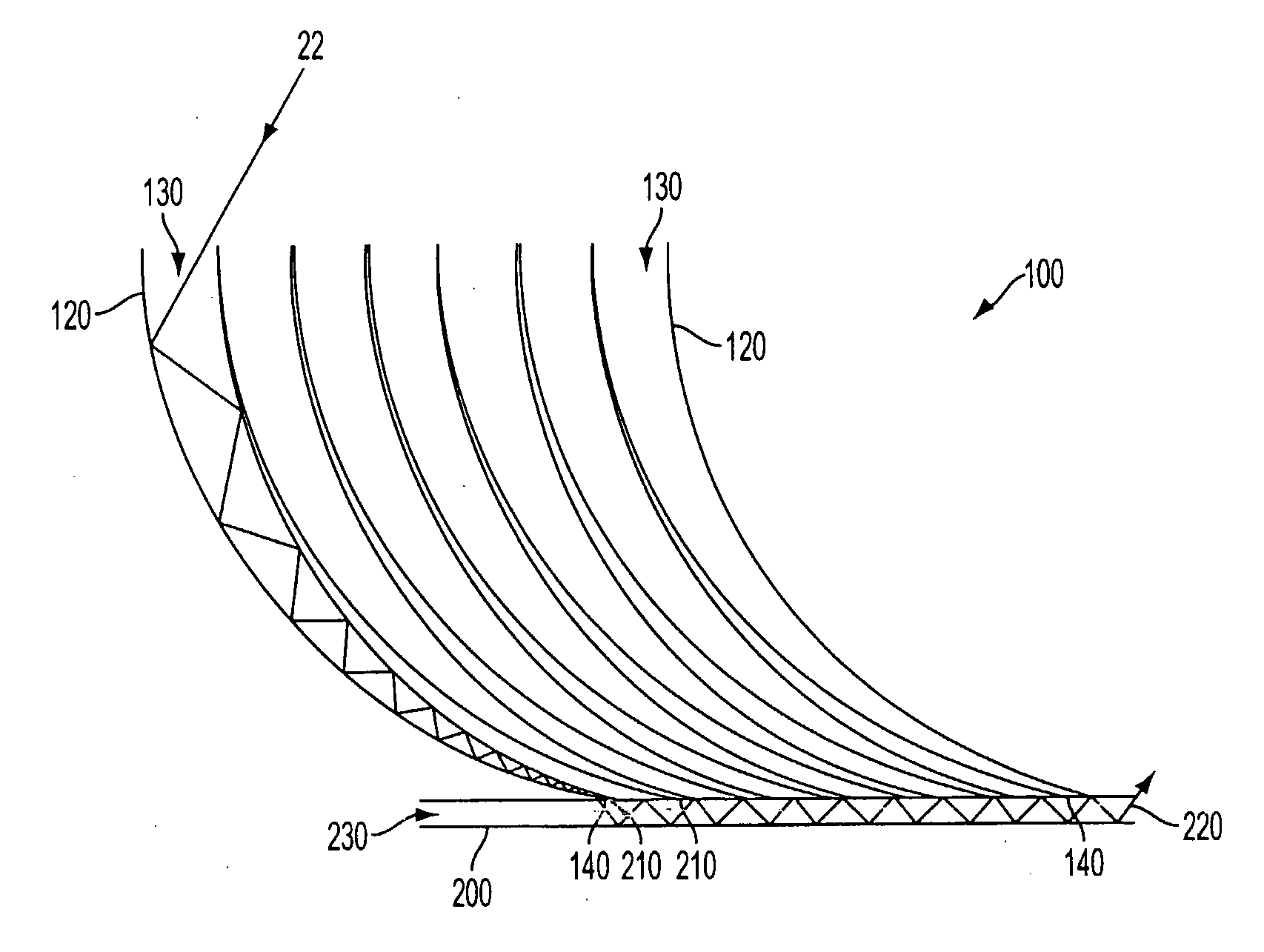
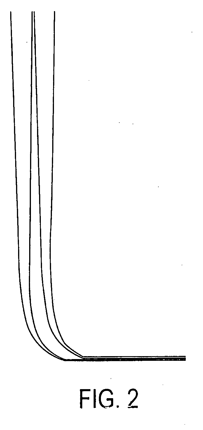
[0022]An example of a device in accordance with the invention has an assembly of channeling areas wherein the EM radiation can be internally reflected within the channeling areas. The channeling areas are constructed such that at least some of the EM radiation that enters a broad end of the channeling areas will be steered within the channeling areas to exit a narrow end of the channeling areas at a direction different to that which it entered. The broad ends of the channeling areas are assembled to form a surface that is herein termed the collection surface. EM radiation falls on the collection surface and enters the broad ends of the channeling areas. The EM radiation is reflected from the walls of the channeling areas so as to be directed to exit from the narrow end of the channeling areas. This is achieved by ensuring that at each reflection point the angle of incidence of the EM radiati...


PUM


Abstract

An electromagnetic radiation collector is provided. The electromagnetic radiation collector has a concentration chamber for collecting and concentrating electromagnetic radiation and directing it to a target, the concentration chamber having at least one inlet opening, the inlet opening having a cross-sectional area. The collector also has a channeling area having an entry end for receiving the electromagnetic radiation, the entry end having a cross-sectional area, an exit end adjacent to the inlet opening of the concentration chamber, and at least one reflective wall between the entry end and the exit end. The cross-sectional area of the inlet opening is smaller than the cross-sectional area of the entry end of the channeling area.

Description

BACKGROUND OF THE INVENTION[0001]1. Field of the Invention[0002]The present invention relates generally to electromagnetic radiation collection.[0003]2. Related Art[0004]The collection and concentration of electromagnetic (EM) radiation is well known. Radio waves are typically collected and concentrated using parabolic dishes. Solar radiation is collected and concentrated using parabolic mirrors or lenses. The former devices suffer from requiring a relatively high height-to-collection area ratio and the latter being expensive, heavy and fragile. Both these types of device also suffer from the requirement to track the source in order to function properly.BRIEF SUMMARY OF THE INVENTION[0005]The invention seeks to overcome at least some of the deficiencies in the prior art by providing an EM radiation collection and concentration device which can cover a large area, have a low profile, have no requirement to track the source and be constructed so as to be relatively light and inexpensi...

Claims


Application Information

Patent Timeline
Patent Type & Authority Applications(United States)
IPC IPC(8): F24J2/10F24S23/00F24S23/70
CPCF24J2/067F24J2/08Y02E10/42F24J2002/003F24J2/12F24S23/71F24S23/12F24S2023/88F24S23/30Y02E10/40
Inventor HODGES, ALASTAIR MCINDOECHAMBERS, GARRY
Owner SUNDAY SOLAR TECH
Learn More