Beryllium-copper conductor

a copper conductor and copper-copper technology, applied in the direction of conductive materials, conductive materials, conductors, etc., can solve the problems of conductor rejection, yellow discoloration, conductor reduction, etc., and achieve the effect of improving the electrical conductivity of c17510 and improving the surface brightness

Inactive Publication Date: 2008-08-28
FISK ALLOY WIRE
View PDF6 Cites 9 Cited by
  • Summary
  • Abstract
  • Description
  • Claims
  • Application Information

AI Technical Summary

Benefits of technology

[0008]The present invention discloses a new alloy composition to improve electrical conductivity of C17510 and improve surface brightness of the silver plated product following final heat treatment.

Problems solved by technology

Attempts to increase one result in reduction of the other.
The higher aging temperature required to age this wire at finish can result in a yellow discoloration.
This discoloration is an unacceptable condition which requires great care to prevent and when ensued is cause for rejection of the conductor.

Method used


Image

  • Beryllium-copper conductor
  • Beryllium-copper conductor
  • Beryllium-copper conductor

Examples


example 1

[0024]A sample of alloy C17510 was obtained with the Ni / Be weight ratio of 6.0. Chemistry of this alloy is listed in Table 2.

TABLE 2Chemical composition for Improved C17510Be, %Ni, %Cu0.321.93Balance

[0025]Performance of this alloy was compared with C17510 having “standard” or typical chemistry for this alloy. Chemical composition of material used for comparison is listed in Table 3. Ni / Be ratio for the standard chemistry sample is 4.4.

TABLE 3Chemical composition for standard C17510Be, %Ni, %Cu0.361.57Balance

[0026]Both the standard and improved wires were obtained in the solutionized condition at 0.0508″ diameter following identical processing. Mechanical properties and electrical conductivity of the as received wires are listed in Table 4. Both versions of the alloy have the same tensile strength and elongation while improved C17510 shows higher electrical conductivity.

TABLE 4Mechanical properties and electrical conductivityof the solution annealed 0.0508″ wireTensileElongation,Cond...

example 2

[0029]The wires of example 1 having the chemistries shown in Tables 2 and 3 were drawn in three steps to 38 AWG (0.004″ in diameter), a typical conductor diameter. As expected, both alloys showed good drawability and could be easily drawn to greater than 99% reduction in area. Properties of the as-drawn wires as a function of cold reduction are listed in Table 6.

TABLE 6Mechanical properties and electrical conductivity ofas-drawn C17510Improved AlloyStandard Alloy% ColdTensileConductivity,TensileConductivity,WorkStrength, ksi% IACSStrength, ksi% IACS0.055.240.555.835.920.874.340.574.036.335.577.639.579.034.949.578.840.782.935.360.880.540.885.536.087.894.638.399.835.599.3117.239.4126.933.6

[0030]The standard chemistry shows a higher work hardening rate but at a lower electrical conductivity. At the highest cold reduction of 99.3% (38 AWG) tensile strength for the standard chemistry is about 10 ksi higher than that of improved C17510.

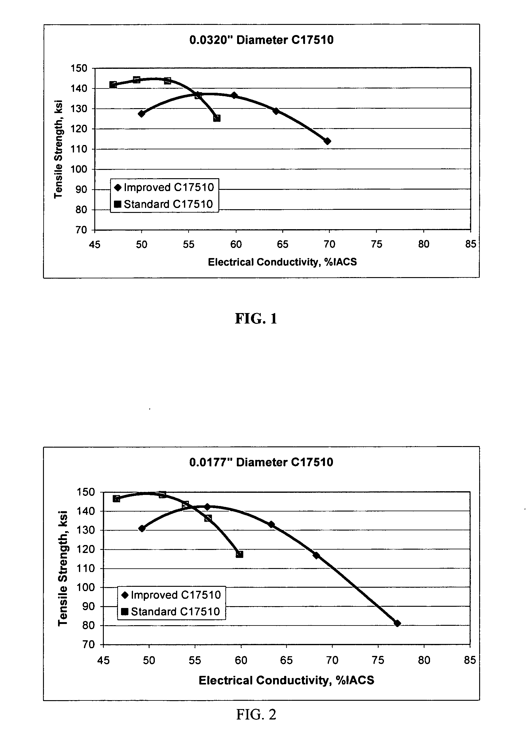
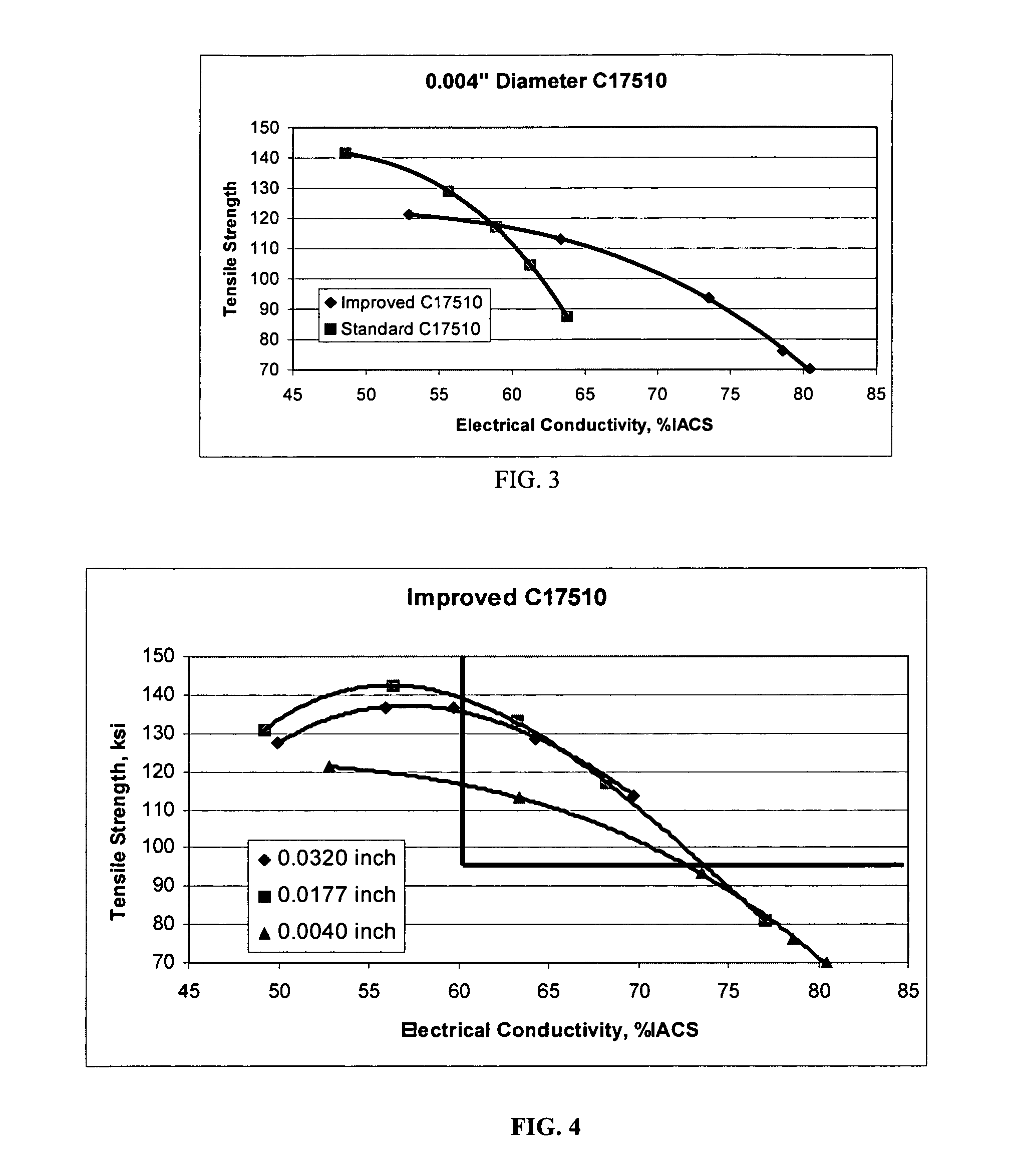
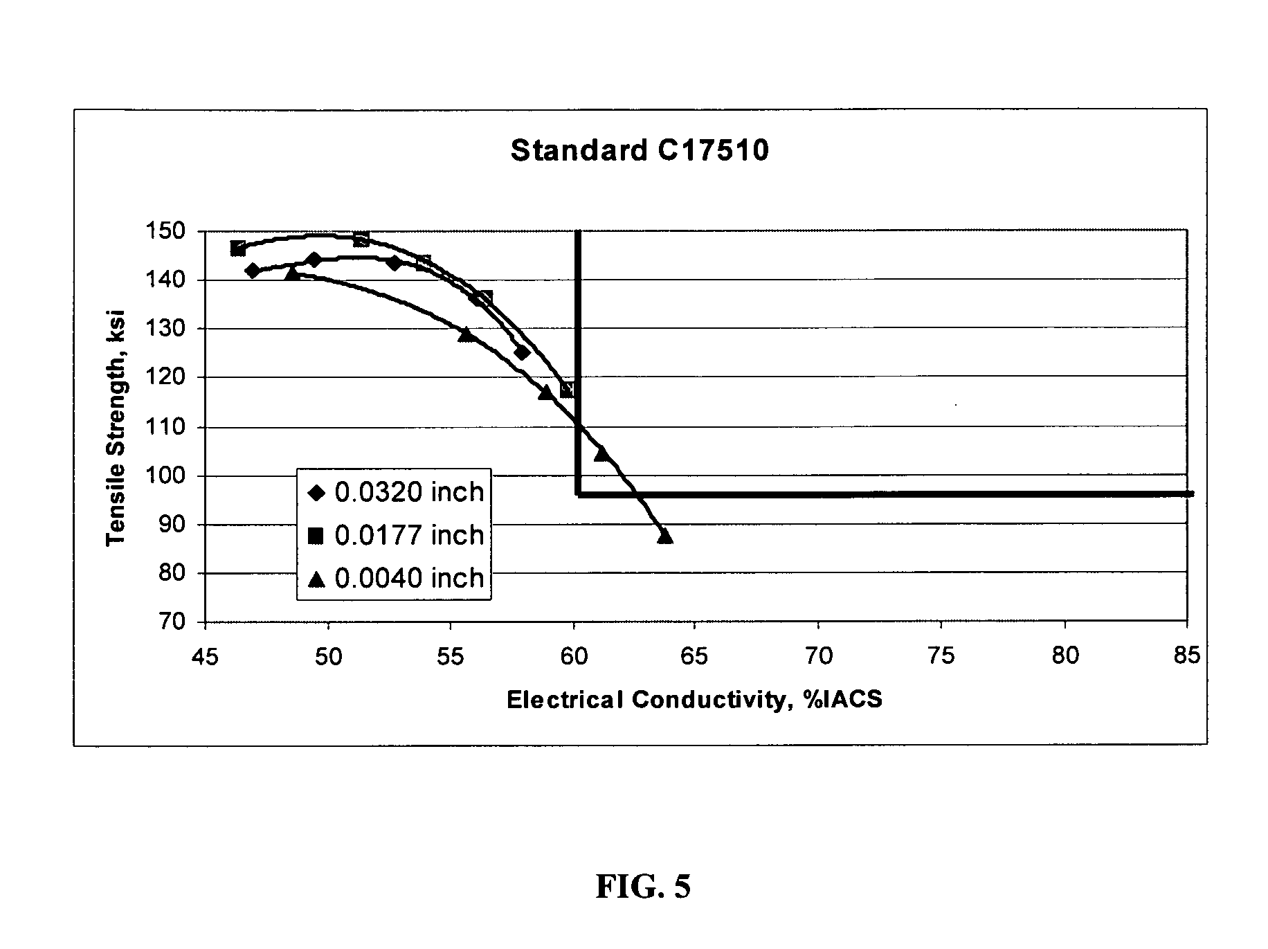
[0031]The wires drawn to 0.0320″, 0.0179″ and 0.004″ ...


PUM

PropertyMeasurementUnit
tensile strengthaaaaaaaaaa
weight ratioaaaaaaaaaa

Abstract

A process is provided for forming an age hardened wire for use as an electrical conductor, which wire is formed from a copper base alloy consisting of from 1.25 to 3.6 wt % nickel, from 0.25 to 0.45 beryllium, and the balance copper and impurities which do not affect the properties of said alloy, with the nickel and beryllium being present in the copper base alloy in a ratio of nickel to beryllium from 5.0 to 8.0. The process comprises the steps of providing a copper base alloy material consisting of from 1.25 to 3.6 wt % nickel, from 0.25 to 0.45 beryllium, and the balance copper and impurities which do not affect the properties of said alloy, which nickel and beryllium are present in the copper base alloy in a ratio of nickel to beryllium from 5.0 to 8.0, cold working the material in a single step; and age hardening the cold worked material in a single step to form a wire in a cold worked and aged hardened condition having an electrical conductivity of at least about 60% IACS.

Description

CROSS REFERENCE TO RELATED APPLICATION(S)[0001]This application claims the priority of U.S. Provisional Patent Application No. 60 / 903,788, entitled Beryllium-Copper Conductor, filed on Feb. 27, 2007.BACKGROUND[0002](1) Field of the Invention[0003]The present invention relates to an, electrical conductor formed from a beryllium-copper alloy which can be formed into a single end or stranded wire.[0004](2) Prior Art[0005]Alloy C17510 is a high conductivity Be—Cu alloy used both as an electronic connector and an electrical conductor. U.S. Pat. Nos. 4,594,116; 4,727,002; and 4,838,959 describe the process and the resultant properties obtained for an electrical conductor using this alloy. The aim is to obtain a product having 95 ksi tensile strength and 60% IACS electrical conductivity. The described process consists of deforming a solution annealed wire greater than 99% cross sectional area followed by over-aging. This process is different than what is normally utilized for this alloy wh...

Claims


Application Information

Patent Timeline
Patent Type & Authority Applications(United States)
IPC IPC(8): C22F1/08C22C9/06
CPCC22C9/06H01B1/026C22F1/08
Inventor SALEH, JOSEPH
Owner FISK ALLOY WIRE
Why Eureka
Try Eureka