
Arc recovery without over-voltage for plasma chamber power supplies using a shunt switch

Active Publication Date: 2008-08-28
AES GLOBAL HLDG PTE LTD
View PDF99 Cites 29 Cited by
  • Summary
  • Abstract
  • Description
  • Claims
  • Application Information

AI Technical Summary

Benefits of technology

[0008]As previously stated, the above-described embodiments and implementations are for illustration purposes only. Numerous other embodiments, implementations, and details of the invention are easily recognized by those of skill in the art from the following descriptions and claims.

Problems solved by technology

After the plasma arc is extinguished, however, the energy circulated within the power supply can cause, for example, an over-voltage condition that can damage the power supply and / or plasma chamber if the energy is released to the plasma chamber.
But many of these components must be large to handle the large number of plasma arcs that can occur, and the energy associated with one or more plasma arcs is dissipated rather than used by the power supply.
Although some circuits can be designed to use the energy associated with a plasma arc by transferring the energy back to an input bus of the power supply, these designs are often quite complex and expensive.
In other words, many current power supply designs are functional but are either too complex, expensive and / or inefficient.

Method used


Image

  • Arc recovery without over-voltage for plasma chamber power supplies using a shunt switch
  • Arc recovery without over-voltage for plasma chamber power supplies using a shunt switch
  • Arc recovery without over-voltage for plasma chamber power supplies using a shunt switch

Examples


Embodiment Construction

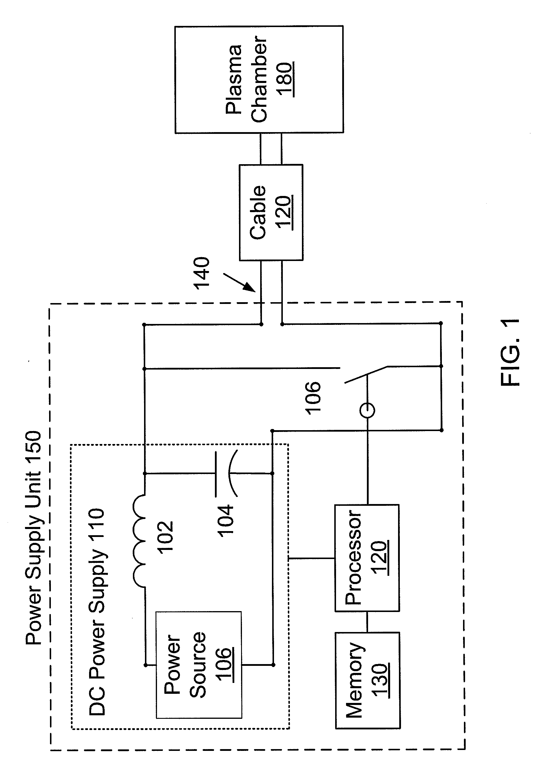
[0019]Referring now to the drawings, where like or similar elements are designated with identical reference numerals throughout the several views, and referring in particular to FIG. 1, it illustrates a power supply unit 150 according to an embodiment of the invention. As shown, a direct current (DC) power supply 110 within the power supply unit 150 is configured to supply power through an output 140 (also referred to as an output port) and via a cable 120 to ignite and / or sustain a plasma in a plasma chamber 180. In some embodiments, the plasma chamber 180 is used, for example, to deposit a thin film on a silicon semiconductor substrate during a semiconductor processing step.

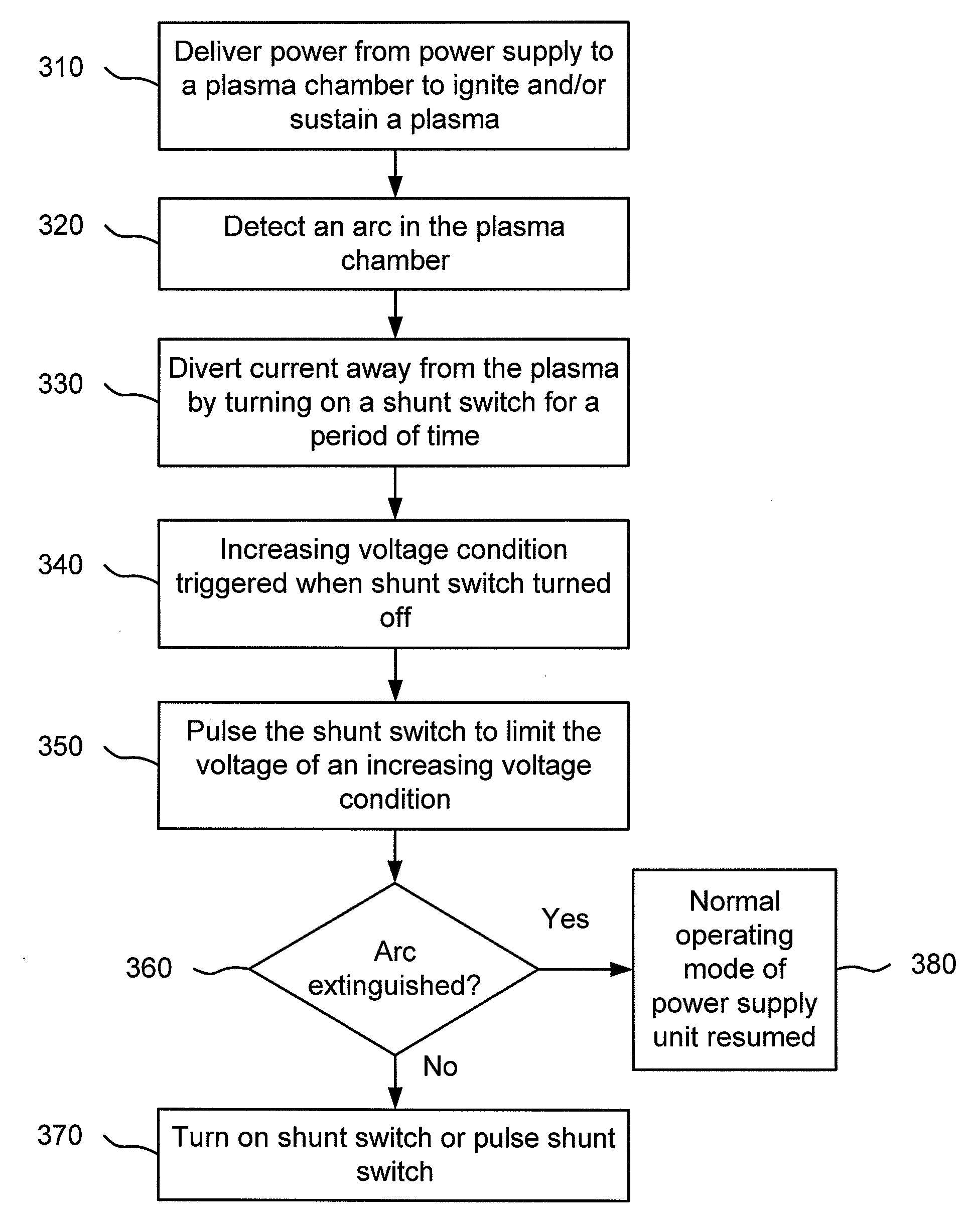
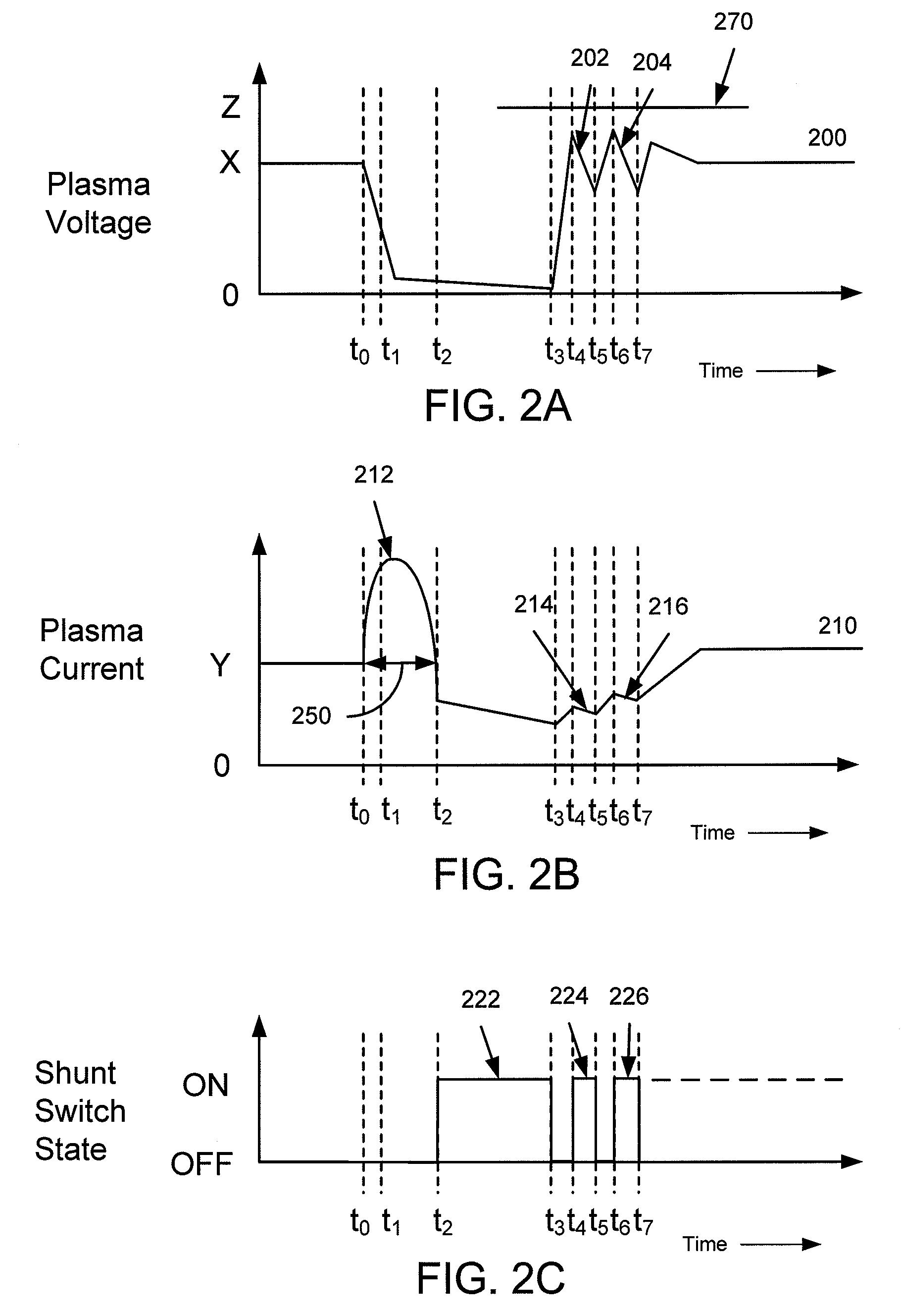
[0020]The processor 120 of the power supply unit 150 is configured to trigger (e.g., toggle) one or more pulse cycles of a shunt switch 106 to mitigate the possibility of over-voltage after a micro arc within the plasma chamber 180 has been extinguished using shunt switch 106. Each of the pulse cycles is trigge...


PUM

PropertyMeasurementUnit
Timeaaaaaaaaaa
Poweraaaaaaaaaa
Electrical inductanceaaaaaaaaaa

Abstract

A system and method for over-voltage protection is described. In one embodiment of the invention, an apparatus includes an output port configured to deliver power to a plasma chamber to ignite a plasma. The apparatus also includes a shunt switch in parallel with the output port and a processor configured to receive an indicator of an arc in the plasma. The processor is configured to close the shunt switch for a period of time to divert current away from the arc. The processor is also configured to trigger a pulse of the shunt switch to limit a voltage of an increasing voltage condition associated with the arc.

Description

FIELD OF THE INVENTION[0001]The present invention relates to plasma chamber power supplies. In particular, but not by way of limitation, the present invention relates to over-voltage protection for plasma chamber power supplies.BACKGROUND OF THE INVENTION[0002]Many power supplies for plasma chambers include an output filter stage that consists of energy storing components such as inductors and capacitors. These output filter stages are often used to, for example, reduce ripple in an output voltage of the power supply. If a plasma arc occurs within a plasma chamber that is receiving power from a power supply of this type, energy can be circulated within the energy storing components of the power supply for a period of time using a shunt switch in order to extinguish the plasma arc. After the plasma arc is extinguished, however, the energy circulated within the power supply can cause, for example, an over-voltage condition that can damage the power supply and / or plasma chamber if the ...

Claims


Application Information

Patent Timeline
IPC IPC(8): B23K9/00
CPCH01J37/32174H05H1/46H01J37/32623H02H3/08G01R31/12H01L21/30
Inventor ILIC, MILANSHILO, VLADISLAV V.HUFF, ROBERT BRIAN
Owner AES GLOBAL HLDG PTE LTD
Learn More