Actuator for control valves and/or shut-off devices

a technology of control valve and actuator, which is applied in the direction of electromagnets, polarised relays, cores/yokes, etc., can solve the problems of low working torque, high cost of motor control means and amplifier means, and low working torque of electric motor drives

Inactive Publication Date: 2008-08-28
BARABAS LAMMERT KURT
View PDF10 Cites 13 Cited by
  • Summary
  • Abstract
  • Description
  • Claims
  • Application Information

AI Technical Summary

Benefits of technology

[0005]The basic object of the present invention is therefore to provide a simple and reliably operating actuator of the type mentioned in the introduction with an adapted, strong actuating force and a general safety position without additional auxiliary energy supply.
[0008]The operating voltage, i.e., the driving energy, can be adapted to the respective actuating force needed with the control and adjusting means provided according to the present invention, and it is also possible to reach any desired intermediate position. The additional advantage that any desired other intermediate position of the parts that actively perform motions, namely, of the moving coil, can be actuated with a corresponding control command from any intermediate position is also important in this connection. Thus, it is possible to perform not only an “on / off” function but also true adjusting functions corresponding to presettable parameters, for example, corresponding to a variable command signal. It is particularly advantageous in this connection that when necessary, the position controller superimposes the position signal to the command signal in such a way that it signals a need for a stronger force and brings about as a result a corresponding increase in the operating voltage applied to the moving coil, which voltage may reach up to 100% of the supply voltage. This advantage is especially significant when the actuation of the actuating element is made difficult by any interfering forces.

Problems solved by technology

While the control means are relatively simple in pneumatic drive units, they do require the presence of a compressed air source, electric motor drives usually require expensive motor control means and amplifier means and optionally additional gear means.
In addition, the working torques that can be attained are low in case of small overall dimensions.

Method used


Image

  • Actuator for control valves and/or shut-off devices
  • Actuator for control valves and/or shut-off devices
  • Actuator for control valves and/or shut-off devices

Examples


Embodiment Construction

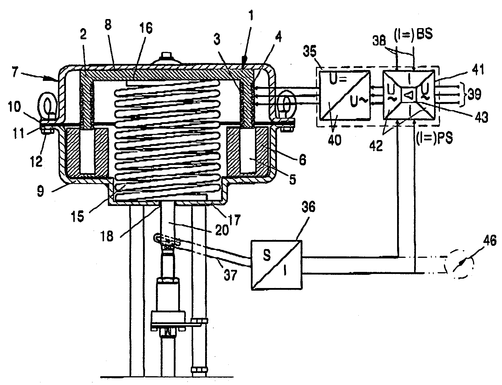
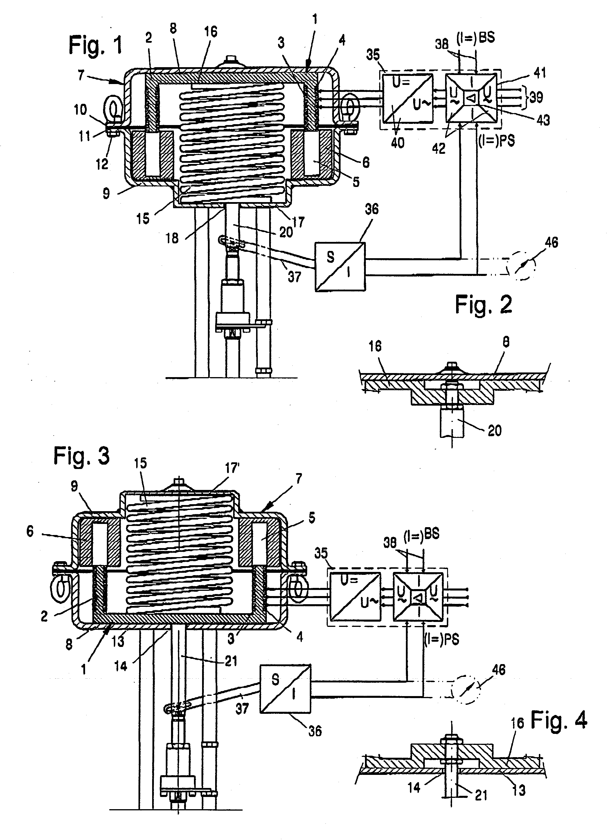
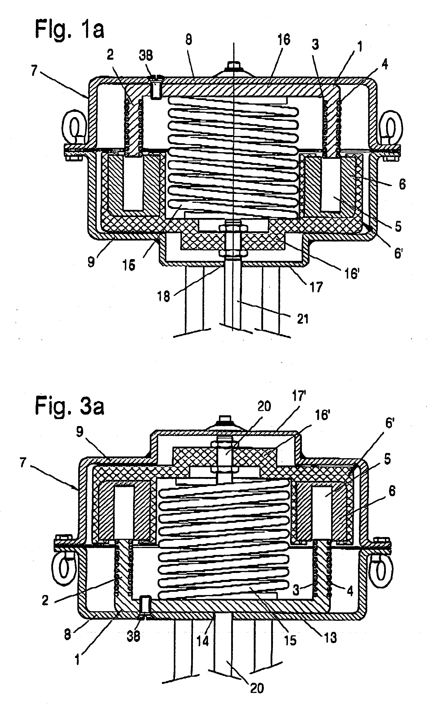
[0023]The actuator for control valves and / or on-off devices, which is shown in a schematically simplified form in FIG. 1, comprises essentially a pot-shaped solenoid plunger 1, at the cylinder wall 2 of which at least one respective magnet coil 3 and 4 is arranged in a firmly seated manner on the inside and / or on the outside. The solenoid plunger 1 is mounted axially movably such that its cylinder wall 2 with the magnet coil or magnet coils 3 and 4 can plunge into an annular groove 5 of a stationarily arranged, axially poled, annular permanent magnet 6.

[0024]The permanent magnet 6 with its annular groove 5 and the solenoid plunger 1 are accommodated in a two-part housing 7, which comprises a pot-shaped upper part 8 and a likewise pot-shaped lower part 9. The upper part 8 and the lower part 9 are provided with movable flanges 10 and 11, respectively, which are detachably connected to one another by means of screws 12.

[0025]The solenoid plunger 1 is provided with a resetting spring 15...


PUM

PropertyMeasurementUnit
current intensityaaaaaaaaaa
voltageaaaaaaaaaa

Abstract

The subject of the present invention is an actuator for control valves and / or shut-off devices with an actuating element acting on a closing or opening element, in which the actuating element comprises a push or pull rod (20, 21), which is in drive connection with the axially movable part of an electromagnetic drive unit designed as a moving coil from a magnet coil (3, 4) and a cylindrical solenoid plunger (1) and is moved into its inoperative position by a resetting spring (15) and is held in that position. To make it possible to use such an actuator instead of the prior-art electric motor, pneumatic or hydraulic drives, provisions are made for the respective actual positions of the actuating element (20, 21) to be detected by an electrical or electronic position controller (36) and transmitted to an electronic actuating amplifier (35), which sends an operating voltage, which is necessary for actuating the actuating element (20, 21) and can be varied between a minimum and a maximum, to the moving coil (3, 4) when a command signal (BS) is present, until the position controller (36) signals the position of the actuating element (20, 21) as feedback, which is preset with the command signal (BS).

Description

CROSS REFERENCE TO RELATED APPLICATIONS[0001]This application claims the benefit of priority under 35 U.S.C. §119 of German Application DE 20 2007 002 760.5 filed Feb. 26, 2007, the entire contents of which are incorporated herein by reference.FIELD OF THE INVENTION[0002]The present invention pertains to an actuator for control valves and / or shut-off devices, such as on-off armatures and the like, with an actuating element, which acts on a closing or opening element, in which the actuating element comprises a push rod or pull rod, which is in drive connection with the axially movable part of an electromagnetic drive unit, which comprises a magnet coil and a cylindrical solenoid plunger and is designed as a moving coil, is moved into its inoperative position by a resetting spring and is held in that position.BACKGROUND OF THE INVENTION[0003]Actuators for control valves and shut-off devices have hitherto been operated almost exclusively pneumatically or by means of electric motors, i....

Claims


Application Information

Patent Timeline
Patent Type & Authority Applications(United States)
IPC IPC(8): H01F7/08
CPCF16K31/0675F16K31/082F16K37/0083H01F7/1607H01F7/1844H01F7/066
Inventor BARABAS-LAMMERT, KURT
Owner BARABAS LAMMERT KURT
Why Eureka
Try Eureka