Integrated-inverter electric compressor

a technology of electric compressor and inverter, which is applied in the direction of dc-ac conversion without reversal, electrical apparatus construction details, printed circuit board receptacles, etc., can solve the problems of easy misalignment of terminals bent upward and extending from the side surface thereof, easy misalignment of terminals, and transmission of vertical vibrations to the inverter device, so as to improve the assembly and vibration resistance of power semiconductor switching devices

Active Publication Date: 2008-08-28
MITSUBISHI HEAVY IND LTD
View PDF5 Cites 44 Cited by
  • Summary
  • Abstract
  • Description
  • Claims
  • Application Information

AI Technical Summary

Benefits of technology

[0012]The present invention was conceived in light of the above circumstances, and an object thereof is to provide an integrated-inverter electric compressor that can enhance assembly and vibration resistance of power semiconductor switching devices and control substrates thereof constituting the inverter device.

Problems solved by technology

However, with the inverter device of the integrated-inverter electric compressor disclosed in the Publication of Japanese Patent No. 3760887, when assembling and mounting the power MOS transistor modules, the terminals bent upward and extending from the side surface thereof are easily misaligned.
Because the number of terminals to be mounted is large (a total of 18 terminals are to be mounted, three terminals being mounted on each of the six power MOS transistor modules), assembly is difficult when fitting them in connecting holes provided in a plate with built-in busbar.
In addition, vertical vibrations are transmitted to the inverter device from the vehicle via the housing of the electric compressor.
These vibrations are also transmitted to the power MOS transistor modules, and, in particular, when an excessive force due to these vibrations is applied to the terminals in the bending direction, the terminals may break, which is problematic in terms of vibration resistance.

Method used


Image

  • Integrated-inverter electric compressor
  • Integrated-inverter electric compressor
  • Integrated-inverter electric compressor

Examples


Embodiment Construction

[0037]An embodiment according to the present invention will now be described with reference to FIGS. 1 to 9.

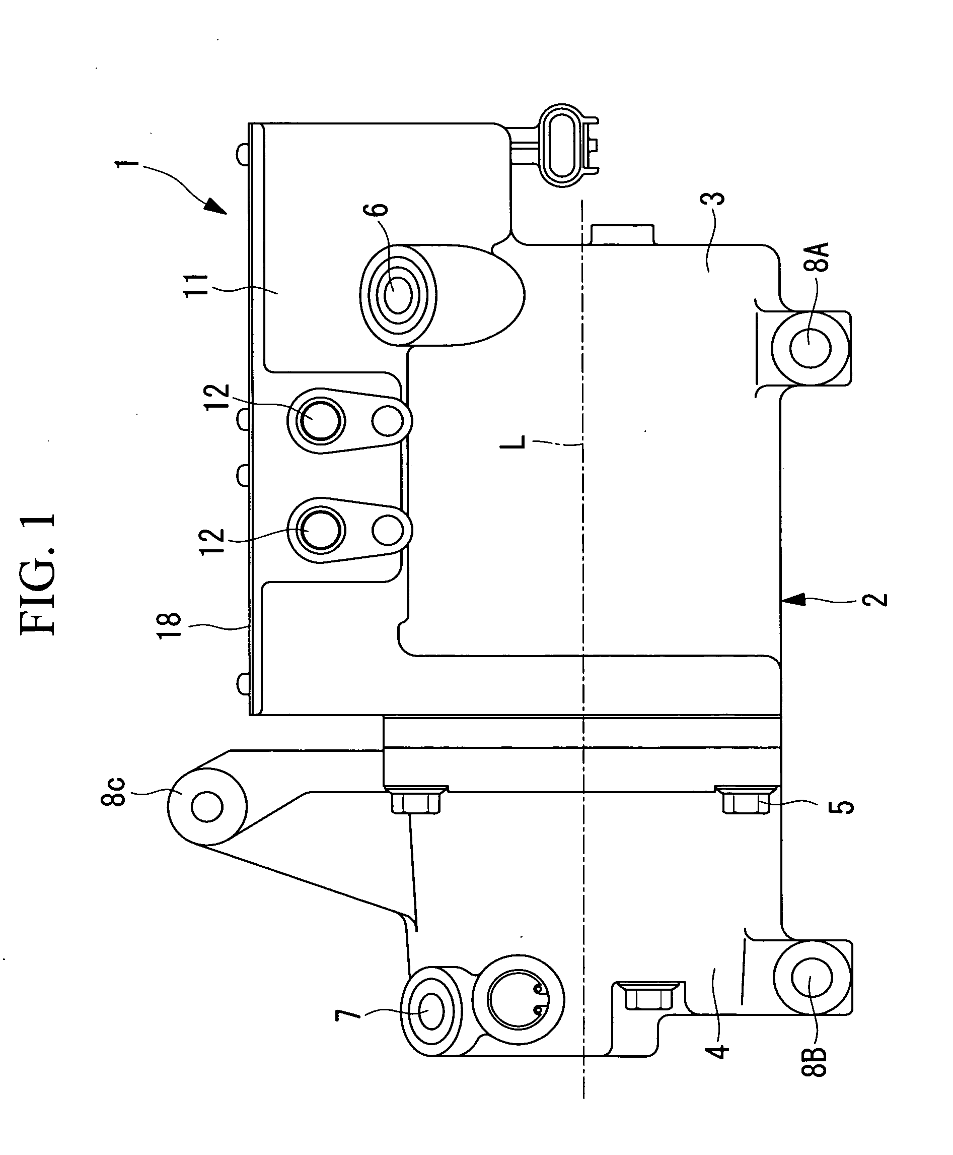
[0038]FIG. 1 is an external side view of an integrated-inverter electric compressor 1 according to one embodiment of the present invention. The integrated-inverter electric compressor 1 includes a housing 2 constituting an outer shell thereof. The housing 2 is constructed by integrally securing a motor housing 3 for accommodating an electric motor, not shown in the drawing, and a compressor housing 4 for accommodating a compressor, not shown in the drawing, by tightening bolts 5. The motor housing 3 and the compressor housing 4 are formed by aluminum die-casting.

[0039]The electric motor and the compressor, which are not shown in the drawing, accommodated in the motor housing 3 and the compressor housing 4, respectively, are linked via a motor shaft, and the compressor is driven as a result of the electric motor being rotated. A suction port 6 is provided at the rear end (on th...


PUM

PropertyMeasurementUnit
heightaaaaaaaaaa
electrical insulatingaaaaaaaaaa
energy efficiencyaaaaaaaaaa

Abstract

An object is to provide an integrated-inverter electric compressor that can enhance assembly and vibration resistance of power semiconductor switching devices and control substrates thereof constituting the inverter device. The integrated-inverter electric compressor, in which an inverter device is installed in an inverter container provided on an outer circumference of a housing, includes a plurality of IGBTs constituting the inverter device and a guide member having a plurality of guide holes for passing terminals of the IGBTs provided between the control substrate and the IGBTs. The guide member is provided with at least one first positioning pin, fitted in positioning holes provided in a mounting surface of the IGBT, in one side surface facing the IGBT, and at least one second positioning pin, fitted in positioning holes provided in the control substrate, in another side surface facing the control substrate.

Description

BACKGROUND OF THE INVENTION[0001]1. Field of the Invention[0002]The present invention relates to an integrated-inverter electric compressor that is particularly suitable for use in an air-conditioning apparatus of a vehicle.[0003]This application is based on Japanese Patent Application No. 2007-049868, the content of which is incorporated herein by reference.[0004]2. Description of Related Art[0005]Recently, the automobile industry has been rapidly promoting the development and commercialization of electrically driven vehicles, such as hybrid vehicles, electric vehicles, and fuel-cell-powered vehicles, to improve energy efficiency.[0006]These vehicles employ air-conditioning apparatuses that, unlike conventional air-conditioning apparatuses, are provided with electric compressors driven by electrically powered motors.[0007]These electric compressors are sealed electric compressors having a compressor and an electric motor in a housing and convert DC power from the power supply into ...

Claims


Application Information

Patent Timeline
Patent Type & Authority Applications(United States)
IPC IPC(8): H02M7/42H02M1/00H05K13/04
CPCY10T29/49169H05K7/1432H05K7/14322
Inventor HATTORI, MAKOTOTAKASHIGE, TAKAYUKINIWA, KAZUKINAKANO, KOJIYAKUSHIJI, SHUNSUKEEBISAWA, MAKOTO
Owner MITSUBISHI HEAVY IND LTD
Why Eureka
Try Eureka