Gating Impact Attenuator

a technology of impact attenuator and gating, which is applied in roadway safety arrangements, roadways, construction, etc., can solve the problems of steel usually showing significant deformation, high kinetic energy management requirements, and higher bending moment loads at groundline,

Inactive Publication Date: 2008-08-28
HUBBELL DAVID ALLEN
View PDF26 Cites 12 Cited by
  • Summary
  • Abstract
  • Description
  • Claims
  • Application Information

AI Technical Summary

Problems solved by technology

Such increases in test vehicle(s) result in both higher kinetic-energy-management requirements and higher bending moment loads at groundline.
Such changes will result in most presently-in-use NCHRP Report 350 rated End Terminal and Crash Cushion installations to be considered, by U.S. transportation agencies, obsolete.
When loaded to failure, steel usually exhibits significant deformation.
In brittle failure, instead of the microstructure's grains “flowing” and thereby opening up voids, usually “downstream” from individual “hard” particles, which are usually well distributed throughout the material's volume, the crystal planes defined by boundaries between individual grains fail.
That is, structural failure is the breaking of the adhesive bonds holding individual grains to each other.
Brittle failure, for a given temperature, in steels considered “ductile”, occur when said ductile steel's volume contains cracks pre-existing before the onset of the brittle failure.
In other cases the drum may be torn away or may be ineffective on leverage grounds in the energy-absorbing interception of a motor vehicle.”
Impracticalities were encountered during numerous full-scale crash testing I conducted on devices similar to that taught by Glaesener '697 and in the process of reducing my U.S. Pat. No. 6,454,488 to practice.
The first issue I've identified is, regardless of the construction and / or materials used for '697 “upright elements”, once laterally loaded by an impacting vehicle, said loaded upright-element deflects away from the applied load.
The third issue I've identified is the need to minimize or eliminate interaction between said impacting vehicle and said impacted upright-element(s) and other upright-element(s) not yet directly engaged by said impacting vehicle.
The fourth issue I've identified is the need to minimize or eliminate interaction between and / or among upright-element pieces which may intentionally or unintentionally become structurally separated due to the vehicle's impact.
1, line 16) “In a roadside barrier having a guard rail held above and parallel to the ground by a plurality of breakaway posts, the end of the guard rail turned toward the oncoming traffic passing the rail creates a considerable hazard.
This projecting end otherwise constitutes a considerable hazard for a motor vehicle striking it.”
Although this prevents the rail from impaling a vehicle colliding with it, it has the extremely dangerous effect of prying the vehicle up and often flipping it over in its own traffic lane or in the opposite traffic lane.
1, line 39) but does not provide workable solutions.
To date, none of the Glaesener-type devices nor these mentioned above address the interplay between highway safety devices that are intended to be highway “crash-cushions” and / or “end-terminals” as defined by NCHRP 350 and vehicle on-board safety devices which are intended to react to impacts.
While there may be present art addressing such concerns, there is no evidence of such being reduced to practice.
Each of these existing TL-2 devices has a complex history of failed testing to achieve a TL-3 rating.
. . straight sections of W-beam.” As such, the ELT and MELT devices lack only an acceptable test 3-31 to have a qualification-free approval as a Test Level 3 device.

Method used


Image

  • Gating Impact Attenuator
  • Gating Impact Attenuator
  • Gating Impact Attenuator

Examples


Embodiment Construction

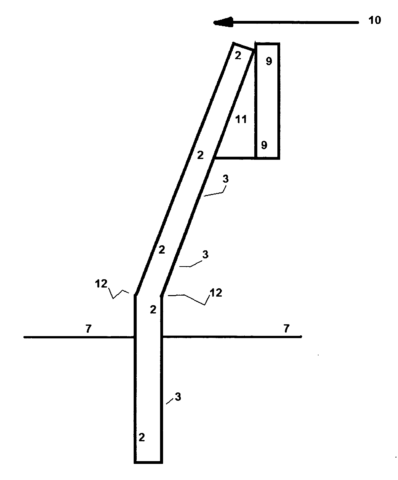
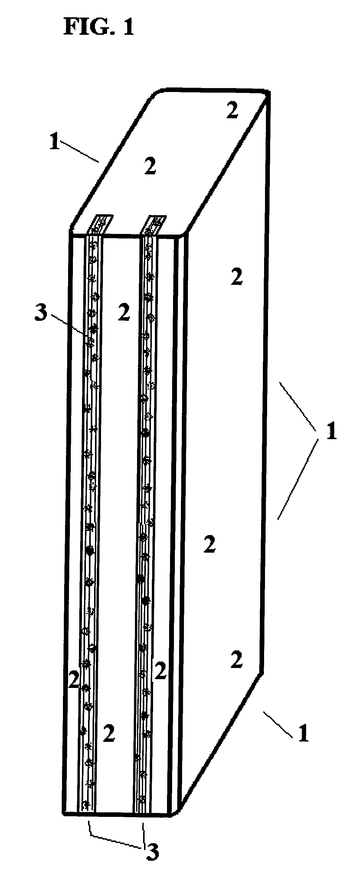
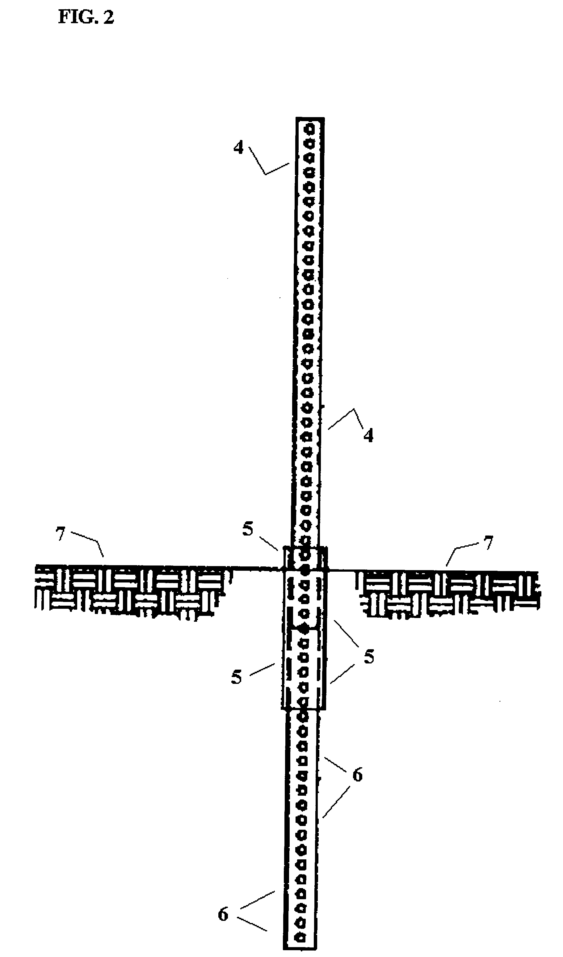
[0100]The present invention utilizes physical dislocations of structural elements to alter the load path(s) of externally imposed loads by changing the effective cross-section of an element via rotation to the imposed shear (shear diagram being constant) in combination with change in dynamic deflection, of a varying nature based on distance from the imposed load to the intended point(s) of structural failure, of the gross structure, thereby increasing the load-time of the imposed load(s). When steel is the material intended for structural failure, particularly “mild” steel, then the response to the imposed load(s), before the onset of structural failure, can be manipulated due to steel's radical increase in tensile strength when dynamically loaded. That is, steel, as a general statement, exhibits a 2 to 3 times increase in tensile load capacity when dynamically loaded vs its load capacity when statically loaded.

[0101]The present invention utilizes the initial kinetic energy of an im...


PUM


Abstract

The present invention relates primarily to highway safety devices, secondarily to on-board vehicle mounted safety devices and more particularly to enhancing the performance of such devices when occupants of vehicles are subjected to severe deceleration forces.

Description

RELATED U.S. APPLICATION DATA[0001]This application claims the benefit of Provisional Application Ser. No. 60 / 819,909, filed Jul. 10, 2006REFERENCES CITED[0002]U.S. Patent Document61,548January 1867Love197,248November 1877Chace322,812July 1885Ellis348,773September 1886Ramsay363,438May 1887Trafton402,790May 1889Waterhouse433,001July 1890Hall498,215May 1893Poehlman524,416August 1894Ewaldt537,621April 1895Stanford555,273February 1896Weber562,297June 1896Haley581,185April 1897Weber593,605111987Pearson609,159August 1898McMahon618,460January 1899Haskell630,577August 1899Westmeyer676,630June 1901McCord1,256,848February 1918Uttz1,284,376November 1918Lehman1,521,579December 1924Freedman1,551,556September 1925Gust1,600,165April 1925Dennebaum1,624,418April 1927Marsh1,808,767June 1931De Gloria et. al.1,915,267June 1933Bigelow2,000,974May 1935Mead2,050,141August 1936Wethington2,088,087July 1937Hudson2,091,195August 1937Dennebaum2,091,925August 1937Heltzel2,146,445February 1939Russert et. al.2,15...

Claims


Application Information

Patent Timeline
Patent Type & Authority Applications(United States)
IPC IPC(8): E01F13/12
CPCE01F15/146E01F15/003
Inventor HUBBELL, DAVID ALLEN
Owner HUBBELL DAVID ALLEN
Why Eureka
Try Eureka