Gait Pattern Generating Device and Controller of Legged Mobile Robot

Active Publication Date: 2008-08-28
HONDA MOTOR CO LTD
View PDF9 Cites 51 Cited by
  • Summary
  • Abstract
  • Description
  • Claims
  • Application Information

AI Technical Summary

Benefits of technology

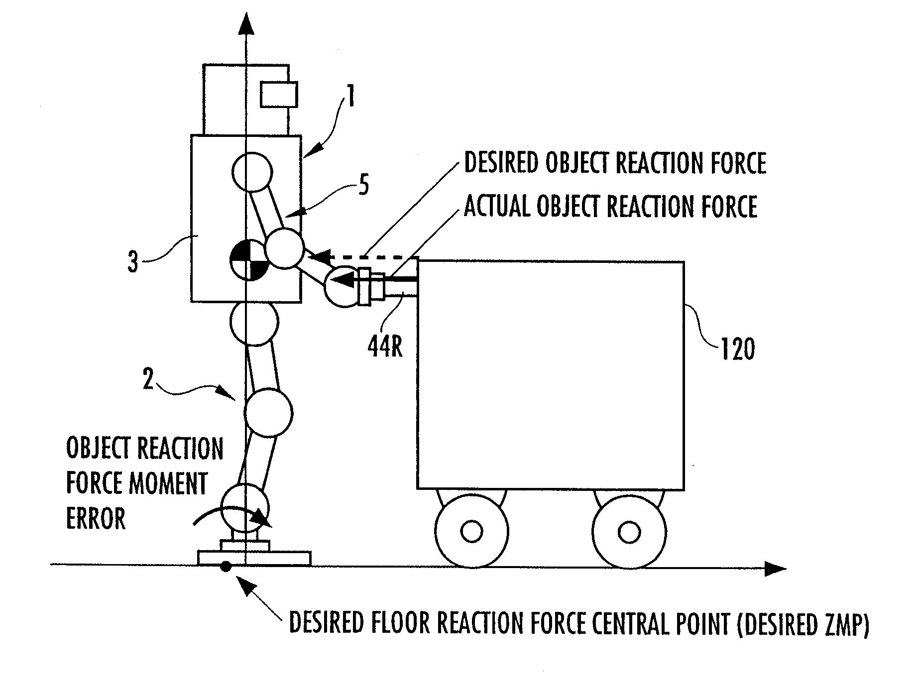
[0043]According to the tenth invention, at least one of a desired motion of the robot and a desired floor reaction force among instantaneous values of a current time gait is corrected so as to bring a difference between an actual external force (real external force) and an instantaneous value of an external force in a current time gait (i.e., an instantaneous value of a desired external force) close to zero on the basis of the differen

Problems solved by technology

And, in such a case, even if the body position/posture of the robot are adjusted to balance a position of the center-of-gravity, the dynamic balance of the robot cannot be immediately secured, leading to a danger that a continuous motion of the robot cannot be stably accomplished.
Further, if a sudden change in an external force takes place in, for example, a case where an operation for moving an object is started by causing an arm or the like of the robot to come in contact

Method used


Image

  • Gait Pattern Generating Device and Controller of Legged Mobile Robot
  • Gait Pattern Generating Device and Controller of Legged Mobile Robot
  • Gait Pattern Generating Device and Controller of Legged Mobile Robot

Examples


first embodiment

[0071]The following will explain in detail a gait generator 100 according to a first embodiment of the present invention. FIG. 5 to FIG. 7 are flowcharts showing the processing by the gait generator 100. The first embodiment is an embodiment of the first to the third inventions, the fifth invention, and the seventh to the tenth inventions of the present invention.

[0072]The gait generator 100 sequentially carries out the processing shown in the flowcharts of FIG. 5 to FIG. 7 at a predetermined calculation processing cycle.

[0073]First, in S01, a moving plan for an object 120 is determined. The moving plan to be determined here includes at least a moving plan for the object 120 for a predetermined future period (for a plurality of steps of the robot 1) from the current time. The moving plan is decided basically according to a moving requirement of the object 120 (a design requirement on a method and timing for moving the object 120), and it is constituted of a position / posture trajecto...

second embodiment

[0249]A second embodiment of the present invention will now be explained with reference to FIG. 20. In the explanation of the second embodiment, the same components or the like functional portions as those in the first embodiment will use the same reference numerals as those in the first embodiment, and the explanation thereof will be omitted. The second embodiment is the embodiment of the first to the third inventions, the fifth invention, and the seventh to the tenth inventions of the present invention.

[0250]The second embodiment differs from the first embodiment only in the processing for correcting a moving plan (the processing that corresponds to the eighth invention of the present invention) in S01 of FIG. 5. This will be explained below. A situation in which the difference between an actual object motion trajectory and a desired object motion trajectory based on a moving plan increases occurs if a relatively large change takes place in a disturbance force other than a force a...

third embodiment

[0257]A third embodiment of the present invention will now be explained with reference to FIG. 21 and FIG. 22. In the explanation of the third embodiment, the same components or the same functional portions as those in the first embodiment will use the same reference numerals as those in the first embodiment, and the explanation thereof will be omitted. The third embodiment is the embodiment of the first, the second invention, the fourth invention, and the sixth to the ninth inventions of the present invention.

[0258]FIG. 21 is a flowchart showing the processing of a part associated with the processing shown in FIG. 5 related to the first embodiment in the processing by a gait generator 100 in the third embodiment. As shown in FIG. 21, the third embodiment differs from the first embodiment only in the processing carried out when a determination result of S19 is NO.

[0259]More specifically, when a determination result of S19 is NO, a desired object reaction force trajectory has been co...


PUM


Abstract

A gait generating system of a legged mobile robot is provided with a device for determining a desired trajectory of an external force to be applied to a robot 1, a device for determining a parameter of a desired gait (current time gait) for a predetermined period on the basis of a desired trajectory of an external force or the like, a device for determining a parameter of a virtual cyclic gait that follows the current time gait on the basis of the desired trajectory of the external force or the like, a device for correcting the current time gait parameter such that a body motion trajectory of the robot 1 of the current time gait converges to a body motion trajectory of the cyclic gait, and a device for sequentially determining an instantaneous value of the current time gait on the basis of the corrected current time gait parameter. With this arrangement, in an environment wherein an external force acts on a robot as necessary, a desired gait that allows continual stability of the robot to be secured can be generated even if the external force suddenly changes.

Description

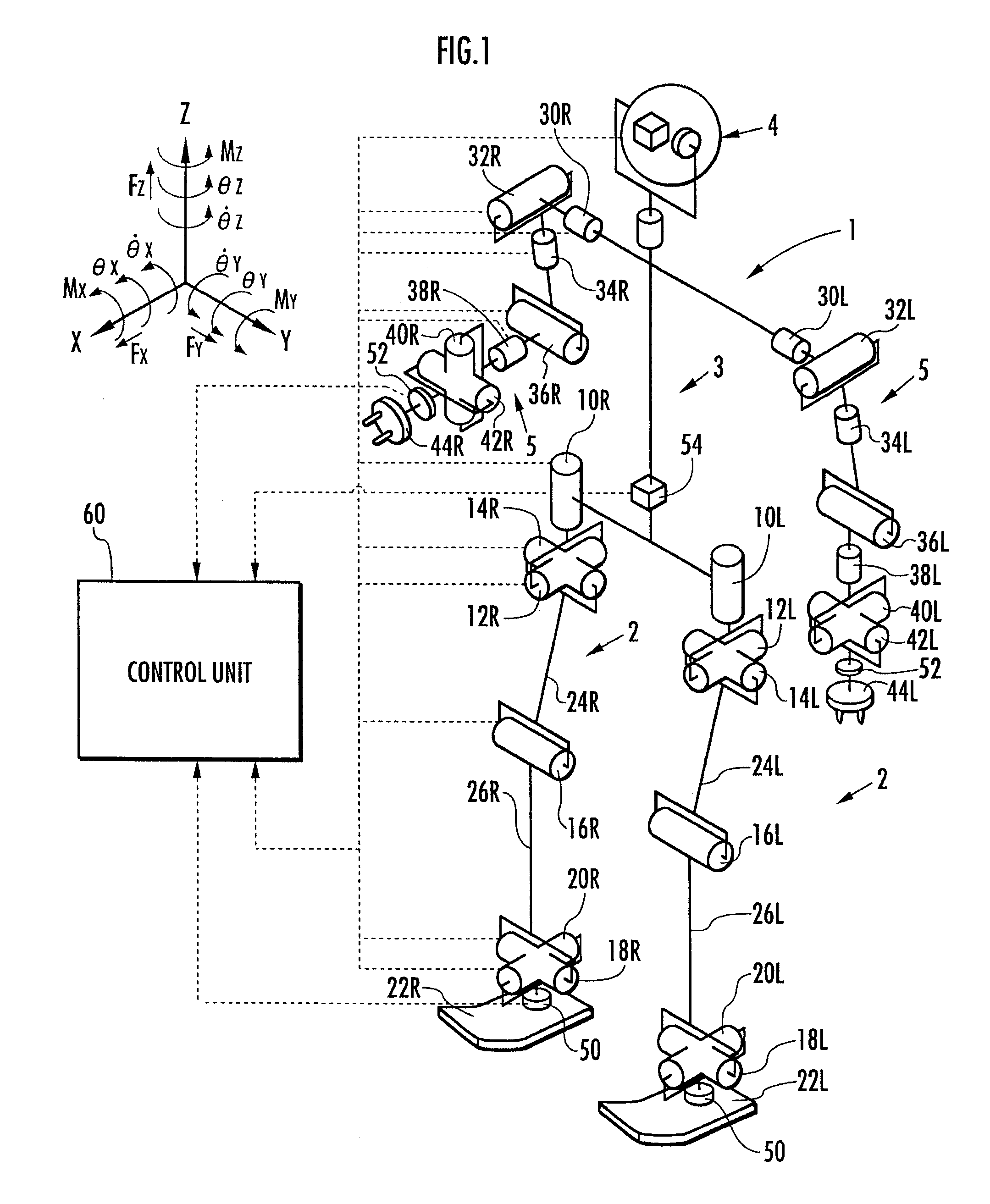
TECHNICAL FIELD[0001]The present invention relates to a gait generating system for generating a gait of a robot in a state wherein an external force other than a floor reaction force is applied to a legged mobile robot as necessary, and a control device for controlling an operation of the robot.BACKGROUND ART[0002]When performing an operation of, for example, pushing a certain object by a legged mobile robot, such as a bipedal mobile robot, the robot is subjected not only to a floor reaction force from a floor with which a distal portion of a leg thereof is in contact but also to a reaction force from the object. A force other than a floor reaction force that is applied to the robot from an external environment will be referred to as an external force in the present description. In particular, an external force (reaction force) that the robot receives from the object will be referred to as an object reaction force. Incidentally, an external force does not include gravitational force...

Claims


Application Information

Patent Timeline
IPC IPC(8): B25J13/00B25J5/00
CPCB62D57/032B25J5/00B25J13/00
Inventor HASEGAWA, TADAAKIOGAWA, NAOHIDE
Owner HONDA MOTOR CO LTD
Why Eureka
Try Eureka