Method of determining a machine operation using virtual imaging

a virtual imaging and machine technology, applied in the direction of picture reproducers, navigation instruments, television signal transmission by single/parallax channels, etc., can solve the problems of limiting the information provided by such tools to textual information and limited image data, affecting the productivity and profitability of the operation, and limiting the information provided by the tool

Active Publication Date: 2008-08-28
CATERPILLAR INC
View PDF15 Cites 133 Cited by
  • Summary
  • Abstract
  • Description
  • Claims
  • Application Information

AI Technical Summary

Benefits of technology

[0008]In one aspect, the present disclosure is directed to a method of determining a machine for operating at an actual site. The method includes establishing a three-dimensional geographical model representing the actual site, determining at least one operation characteristic relating to the operation of each of a set of machines in relation to the model, and predicting at least one performance characteristic for each machine based on the at least one operation characteristic and at least one respective characteristic of each machine. The method also includes comparing the predicted performance characteristics for each machine, and determining a target machine based on the comparison.
[0009]In another aspect, the present disclosure is directed to a system for managing a machine at a site. The system includes a controller, and the controller includes a user interface configured to display a three-dimensional geographical model representing a plurality of remote sites. The controller is configured to receive input identifying one of the remote sites, determine an operation of the machine in relation to the model at the selected site, determine at least one operation characteristic relating to the operation of the machine, and predict at least one performance characteristic of the machine based on the at least one operation characteristic and at least one characteristic of the machine.
[0010]In yet another aspect, the present disclosure is directed to a method of planning an operation of a machine at an actual site. The method includes establishing a three-dimensional geographical model representing the actual site, determining a sales price for at least one material located at the actual site, determining the machine, and determining at least one operation characteristic relating to the operation of the machine in relation to the model. The at least one operation characteristic includes an amount of material excavated. The method also includes predicting at least one performance characteristic for the machine based on the at least one operation characteristic and at least one characteristic of the machine. The at least one performance characteristic includes an estimated profit associated with the machine.

Problems solved by technology

For example, the grade and character of haul routes and the amount of payload have direct effects on haulage cycle time, equipment component wear, and fuel consumption which, in turn, directly affect productivity and profitability of the operation.
However, the information provided by such tools may be restricted to textual information and limited image data, such as a two-dimensional map of a work site or a two-dimensional image of a product.
Although the system of the '949 patent may provide a tool for visualizing the operation of a machine, the information provided by the tool is limited.
In addition, the visualization tool only incorporates elevation information of the work site, thereby including a limited amount of information describing the work site and limiting the ability of the tool to provide an accurate prediction of the excavation result.
Furthermore, the visualization tool is used to make decisions about the excavation operation in real-time and not for more comprehensive long-term site solution planning.
For example, the visualization tool does not allow adjusting the number of machines at the work site.
Therefore, the user of the visualization tool cannot effectively optimize the efficiency of the excavation operation.
Also, the visualization tool is limited to visualizing the operations of the machine within the boundaries of the material to be excavated or the operational limits of the machine.
Therefore, the visualization tool is limited to a single work site, and the user cannot compare the characteristics of more than one work site to make a proper determination of where to excavate.

Method used


Image

  • Method of determining a machine operation using virtual imaging
  • Method of determining a machine operation using virtual imaging
  • Method of determining a machine operation using virtual imaging

Examples


Embodiment Construction

[0016]Reference will now be made in detail to the present exemplary embodiments of the invention, examples of which are illustrated in the accompanying drawings. Wherever possible, the same reference numbers will be used throughout the drawings to refer to the same or like parts.

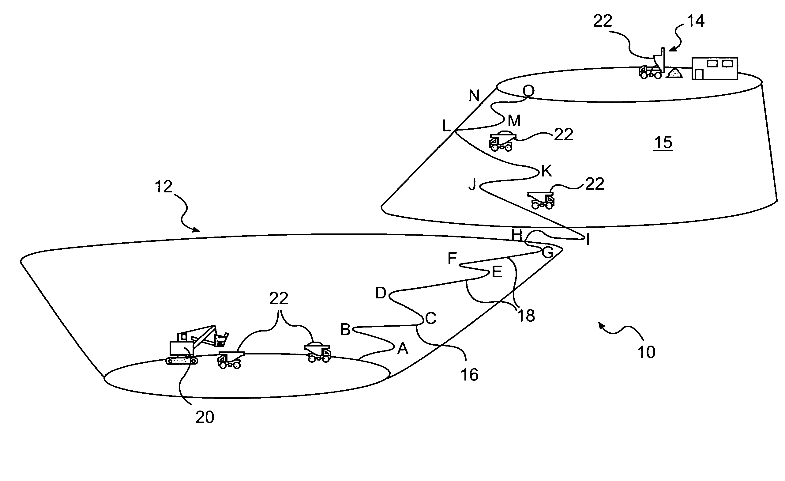
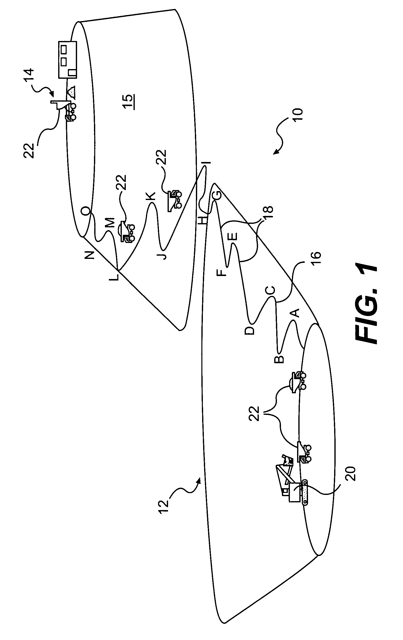
[0017]FIG. 1 schematically and diagrammatically illustrates a work site 10, such as an open pit mine operation. The open pit mine operation 10 includes an open pit mine 12 and a processing region 14, which may be, but is not required to be, on top of a dumping mound 15. The open pit mine 12 is connected to the processing region 14 by at least one haul route 16, which includes haul route segments 18 between designated letters A, B, C, etc. A fleet of machines 20, such as haulage vehicles 22 and / or other types of machines, may travel from the area of excavation of the open pit mine 12 along the haul route 16 to the processing region 14. In the open pit mine 12, another machine 20, such as an excavator, may ope...


PUM


Abstract

A method of determining a machine for operating at an actual site includes establishing a three-dimensional geographical model representing the actual site, determining at least one operation characteristic relating to the operation of each of a set of machines in relation to the model, and predicting at least one performance characteristic for each machine based on the at least one operation characteristic and at least one respective characteristic of the different machines. The method further includes comparing the predicted performance characteristics for the different machines, and determining a target machine based on the comparison.

Description

TECHNICAL FIELD[0001]The present disclosure relates generally to a method of determining operation characteristics, and more particularly, to a method of determining operation characteristics using virtual imaging.BACKGROUND[0002]Mining and large scale excavating operations may require fleets of haulage vehicles to transport excavated material, such as ore or overburden, from an area of excavation to a destination. For such an operation to be productive and profitable, the fleet of haulage vehicles must be efficiently operated. Efficient operation of a fleet of haulage vehicles is affected by numerous operation characteristics. For example, the grade and character of haul routes and the amount of payload have direct effects on haulage cycle time, equipment component wear, and fuel consumption which, in turn, directly affect productivity and profitability of the operation.[0003]Computer-aided design (CAD) and visualization tools may be used to design, develop, and manufacture the hau...

Claims


Application Information

Patent Timeline
Patent Type & Authority Applications(United States)
IPC IPC(8): G06F17/50G01C21/34
CPCY02T10/82E21C41/26
Inventor VIK, TIMOTHY ALLEN
Owner CATERPILLAR INC
Why Eureka
Try Eureka