Threat Launch Detection System and Method

a detection system and threat technology, applied in the field of sensors, can solve the problems of limiting the types of threats that can be reliably detected, affecting the detection accuracy of target detection systems, and limiting the time for acquisition and processing, so as to achieve the effect of reliably detecting short-burn threats such as tank shells or rpgs

Active Publication Date: 2008-08-28
BAE SYST INFORMATION & ELECTRONICS SYST INTERGRATION INC
View PDF13 Cites 13 Cited by
  • Summary
  • Abstract
  • Description
  • Claims
  • Application Information

AI Technical Summary

Benefits of technology

[0016]According to one aspect of the present invention, a threat launch detection system includes at least one temporal threat detector, each temporal threat detector including a single sensing element operable to sense radiation from various types of short-burn threats that occur within a field of view of the detector. The single sensing element generates a detection signal in response to the sensed radiation. A processing circuit is coupled to each temporal threat detector and is operable to analyze the detection signal from each detector as a function of time to detect the occurrence of a short-burn threat within the field

Problems solved by technology

This is true partially because the time for acquisition and processing required to analyze the frames captured by each sensor array is relatively intensive, and, as previously mentioned, numerous sensor arrays are required to provide the required overall field of view for the system.
This intensive processing caused by the multiple sensor arrays and the large number of pixels per sensor array limits the rate at which the system can operate and thereby limits the types of threats that can be reliably detected.
Short-burn threats such as tank shells or RPGs are accordingly not reliably detected by conventional threat launch detection systems.
If the threat is not present in each of these frames, however, such as may be the case for short-burn type threats where the threat may only be present in one or two frames, the system determines the threat is false.
With these conventional threat launch detection systems, even though a real threat such as an RPG has been directed at the target containing the system, the system has problems reliably detecting the short-burn threat.
Thus, although the sensors typically “see” the threat, meaning at least some pixels in at least one sensor detect the presence of the threat, the

Method used


Image

  • Threat Launch Detection System and Method
  • Threat Launch Detection System and Method
  • Threat Launch Detection System and Method

Examples


Embodiment Construction

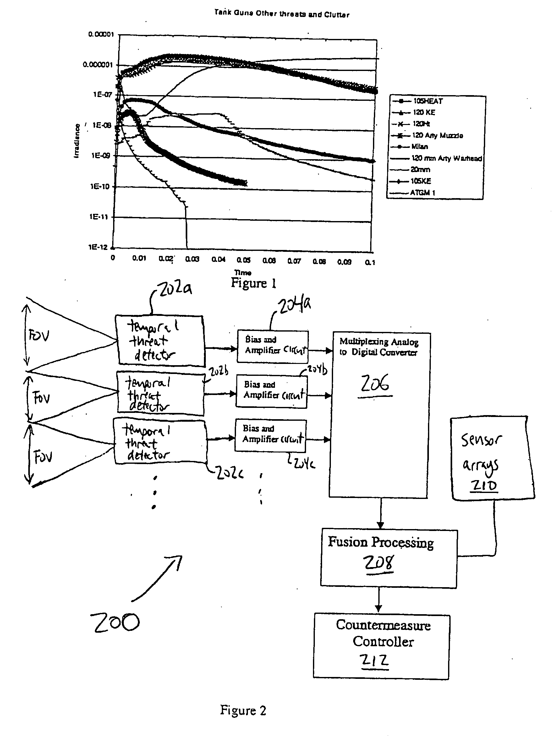
[0023]Before describing several embodiments of the present invention, the characteristics of several types of short-burn threats will be discussed with reference to FIG. 1. FIG. 1 is a graph showing irradiance as a function of time for various types of short-burn threats and clutter. Various short-burn threats and threat like events on the battlefield are distinct when observed or sensed at a frequency of 1000 Hz or above. FIG. 1 shows a sampling of such threats as measured by a fast radiometer, including several antitank guided missile time sequences with direct fire gun blasts, indirect fire artillery, warhead events, and machine gun fire. These sequences are all measured data from events at various distances from the radiometer.

[0024]FIG. 1 shows that a sensor capable of distinguishing threats would need a minimum of 20 pw / cm2 sensitivity and a top end of about 2×10⁻⁶ or about 1×10⁵:1 dynamic range. The figure illustrates that temporal profiling to distinguish typical short-burn ...


PUM


Abstract

A threat launch detection system includes at least one temporal threat detector, each temporal threat detector including a single sensing element operable to sense radiation from various types of short-burn threats that occur within a field of view of the detector. The single sensing element generates a detection signal in response to the sensed radiation. A processing circuit is coupled to each temporal threat detector and is operable to analyze the detection signal from each detector as a function of time to detect the occurrence of a short-burn threat within the field of view of any of the temporal threat detectors. Each temporal threat detector may be a prism-coupled compound parabolic concentrator (PCCP).

Description

CROSS REFERENCE TO RELATED APPLICATIONS[0001]This application claims priority from U.S. Provisional Application No. 60 / 542,042, filed 5 Feb. 2004, which is incorporated herein by reference.STATEMENT OF GOVERNMENT INTEREST[0002]The invention was made with United States Government support under Contract (Grant) No. DMEA90-99-D-007 awarded by DMEA. The United States Government has certain rights in this invention.TECHNICAL FIELD[0003]The present invention relates generally to sensors and more particularly to threat warning detectors for short-burn and motorless threats such as tube launched missiles and direct fire projectiles.BACKGROUND OF THE INVENTION[0004]A threat launch detection system is a system that detects a weapon that is being directed at a target, with the target typically containing the threat launch detection system. In response to detecting a weapon directed at the target, which will be referred to as a threat or event throughout the present description, the threat laun...

Claims


Application Information

Patent Timeline
IPC IPC(8): G06F15/00
CPCF41H11/02G01J1/04G01J1/0407G01S7/495G01J1/42G01S7/38G01J1/0422
Inventor WEBER, JONATHAN L.MANDZY, JOHNEGBERT, PAUL I.SMITH, KIRBY A.SHEA, JILL A.
Owner BAE SYST INFORMATION & ELECTRONICS SYST INTERGRATION INC
Why Eureka
Try Eureka