Packet-Based Parallel Interface Protocol For A Serial Buffer Having A Parallel Processor Port

Inactive Publication Date: 2008-08-28
INTEGRATED DEVICE TECH INC
View PDF35 Cites 26 Cited by
  • Summary
  • Abstract
  • Description
  • Claims
  • Application Information

AI Technical Summary

Problems solved by technology

However, connecting a system processor to a serial buffer typically requires a specialized port hardware and a relatively complicated link layer protocol.
These factors undesirably

Method used


Image

  • Packet-Based Parallel Interface Protocol For A Serial Buffer Having A Parallel Processor Port
  • Packet-Based Parallel Interface Protocol For A Serial Buffer Having A Parallel Processor Port
  • Packet-Based Parallel Interface Protocol For A Serial Buffer Having A Parallel Processor Port

Examples


Embodiment Construction

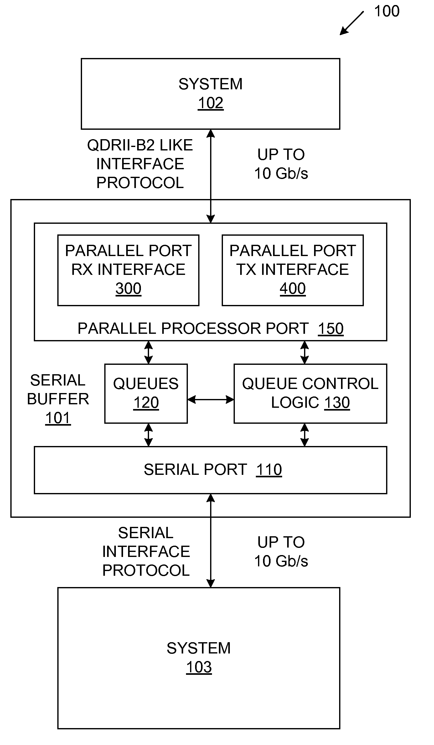
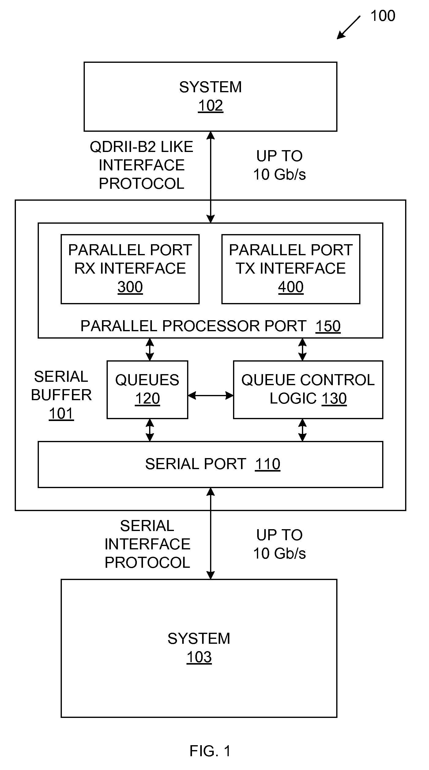
[0017]FIG. 1 is a block diagram of a system 100, which includes serial buffer 101 and systems 102-103. System 102 may represent, for example, a processor, memory or field programmable gate array. Similarly, system 103 may represent, for example, a switch or a memory. Transfers between serial buffer 101 and system 103 are performed in accordance with a serial protocol, such as sRIO, SerialLite, or Aurora. In the described examples, transfers between serial buffer 101 and system 103 take place on 32-bit wide data buses at speeds up to 10 Gb / s.

[0018]In accordance with one embodiment of the present invention, serial buffer 101 includes parallel processor port 150, a plurality of queues 120 and queue control logic 130 and at least one serial port 110. Parallel processor port 150 (along with queue / queue control logic 120 / 130) enables communications between system 102 and the serial port 110 of serial buffer 101, such that system 102 can communicate with system 103 through serial buffer 10...


PUM


Abstract

A serial buffer is provided having a parallel port configured to couple the serial buffer to a first system via a parallel interface protocol. The serial buffer also includes a serial port configured to couple the serial buffer to a second system via a serial interface protocol and control logic that enables data to be transferred between the parallel port and the serial port in an efficient manner. In one embodiment, the parallel interface protocol is substantially identical to a quad-data rate burst of two (QDRII-B2) interface protocol.

Description

RELATED APPLICATIONS[0001]The present application is related to the following commonly-owned, co-filed U.S. Patent applications, which are hereby incorporated by reference in their entirety:[0002]U.S. patent application Ser. No. ______ [Attorney Docket No. IDT-2211]“METHOD AND STRUCTURE TO SUPPORT SYSTEM RESOURCE ACCESS OF A SERIAL DEVICE IMPLEMENTING A LITE-WEIGHT PROTOCOL”, by Chi-Lie Wang, Jason Z. Mo and Calvin Nguyen.[0003]U.S. patent application Ser. No. ______ [Attorney Docket No. IDT-2212]“HARDWARE-BASED CONCURRENT DIRECT MEMORY ACCESS (DMA) ENGINES ON SERIAL RAPID INPUT / OUTPUT SRIO INTERFACE”, by Chi-Lie Wang and Bertan Tezcan.[0004]U.S. patent application Ser. No. ______ [Attorney Docket No. IDT-2213]“RAPID INPUT / OUTPUT DOORBELL COALESCING TO MINIMIZE CPU UTILIZATION AND REDUCE SYSTEM INTERRUPT LATENCY”, by Chi-Lie Wang, Kwong Hou (“Ricky”) Mak and Jason Z. Mo.[0005]U.S. patent application Ser. No. ______ [Attorney Docket No. IDT-2214]“MULTI-BUS STRUCTURE FOR OPTIMIZING SY...

Claims


Application Information

Patent Timeline
IPC IPC(8): G06F13/38
CPCG06F13/385
Inventor MO, JASON Z.HRONIK, STANLEY
Owner INTEGRATED DEVICE TECH INC
Why Eureka
Try Eureka