
Exhaust throttle valve diagnosing device and method

a technology of exhaust throttle valve and diagnostic device, which is applied in the direction of exhaust treatment electric control, electrical control, machines/engines, etc., can solve the problems of power capacity, exhaust gas deterioration, and inability to diagnose mechanical failure, so as to facilitate the simple detection of mechanical failure of exhaust throttle valv

Inactive Publication Date: 2008-09-04
ISUZU MOTORS LTD
View PDF7 Cites 49 Cited by
  • Summary
  • Abstract
  • Description
  • Claims
  • Application Information

AI Technical Summary

Benefits of technology

[0012]It is an object of the present invention to provide an exhaust throttle valve diagnosing device and method that, in resolving the aforementioned problems, facilitates a simple detection of the mechanical failure of an exhaust throttle valve caused by sticking or the like.

Problems solved by technology

However, conventional failure diagnosis such as this has the inherent problem of facilitating only an electrical failure diagnosis and, accordingly, it does not allow for diagnosis of mechanical failure such as that due to close sticking or open sticking of the exhaust throttle valve due to soot or the like.
A concern inherent to an exhaust throttle valve sticking in this way is that it will cause imperfect engine warm-up, power capacity / exhaust gas deterioration due to exhaust resistance, imperfect DPD regeneration, as well as the misdiagnosis of other diagnoses that use air flow rate measurement resulting in erroneous failsafe indications.
However, because the exhaust throttle valve constitutes an exhaust system component part there are temperature and vibration-related problems, as well as a cost-related problem inherent thereto, and the supplementary provision of an opening degree sensor and so on thereon involves a mounting step that is difficult to implement.
In addition, because the exhaust throttle valve requires no precise opening degree control and is basically ON / OFF controlled, mounting an opening degree sensor for the purpose of diagnosis alone is undesirable from the viewpoint of cost.

Method used


Image

  • Exhaust throttle valve diagnosing device and method
  • Exhaust throttle valve diagnosing device and method
  • Exhaust throttle valve diagnosing device and method

Examples


Embodiment Construction

[0024]The “exhaust throttle valve diagnosing device and method” described by the specification, claims and drawings of this application is described in Japanese Patent Application No. 2007-53042.

[0025]A preferred embodiment of the present invention will be hereinafter described with reference to the attached drawings.

[0026]The exhaust throttle valve diagnosing device (hereinafter the diagnosing device) of this embodiment has application in, for example, an automotive vehicle diesel engine.

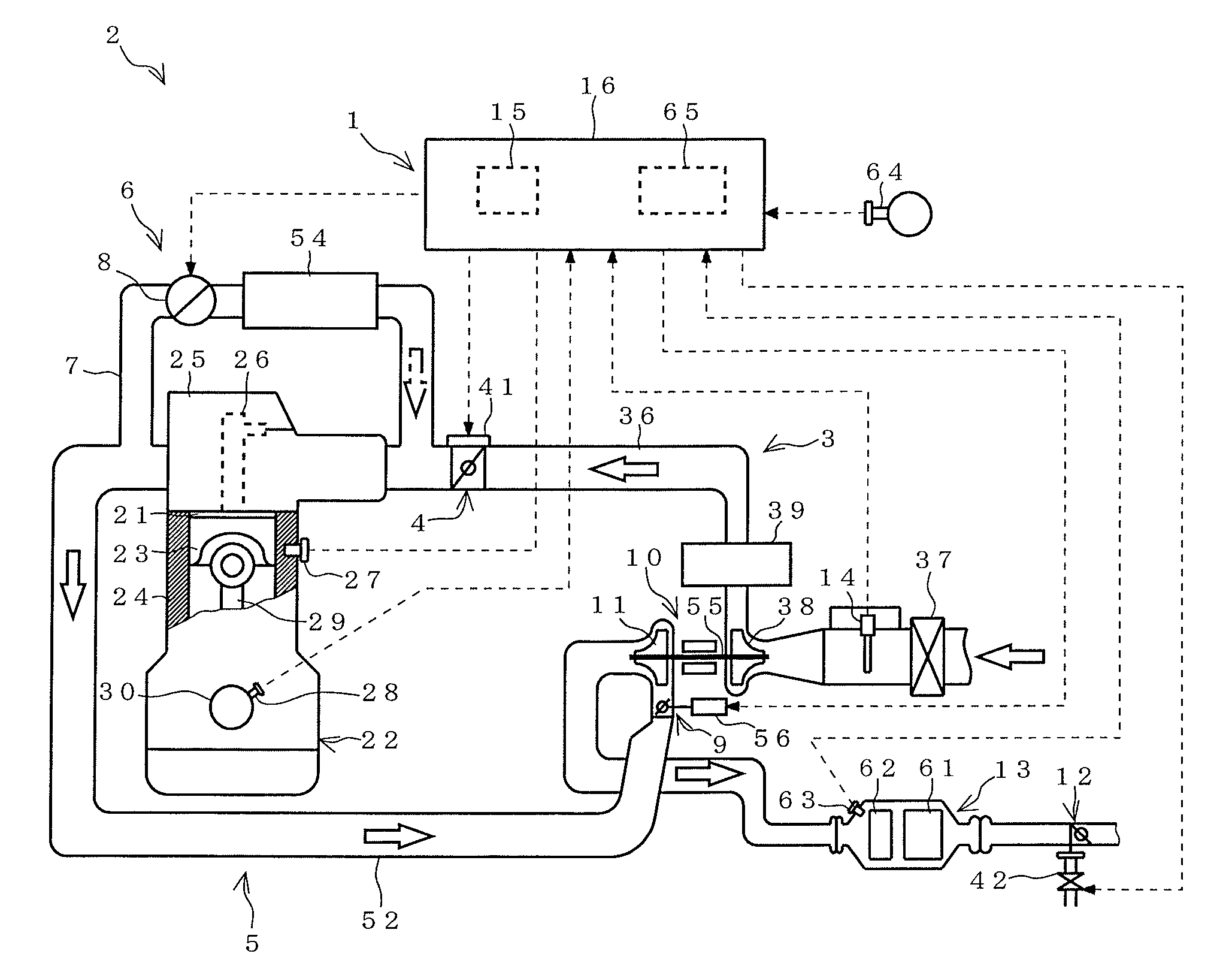
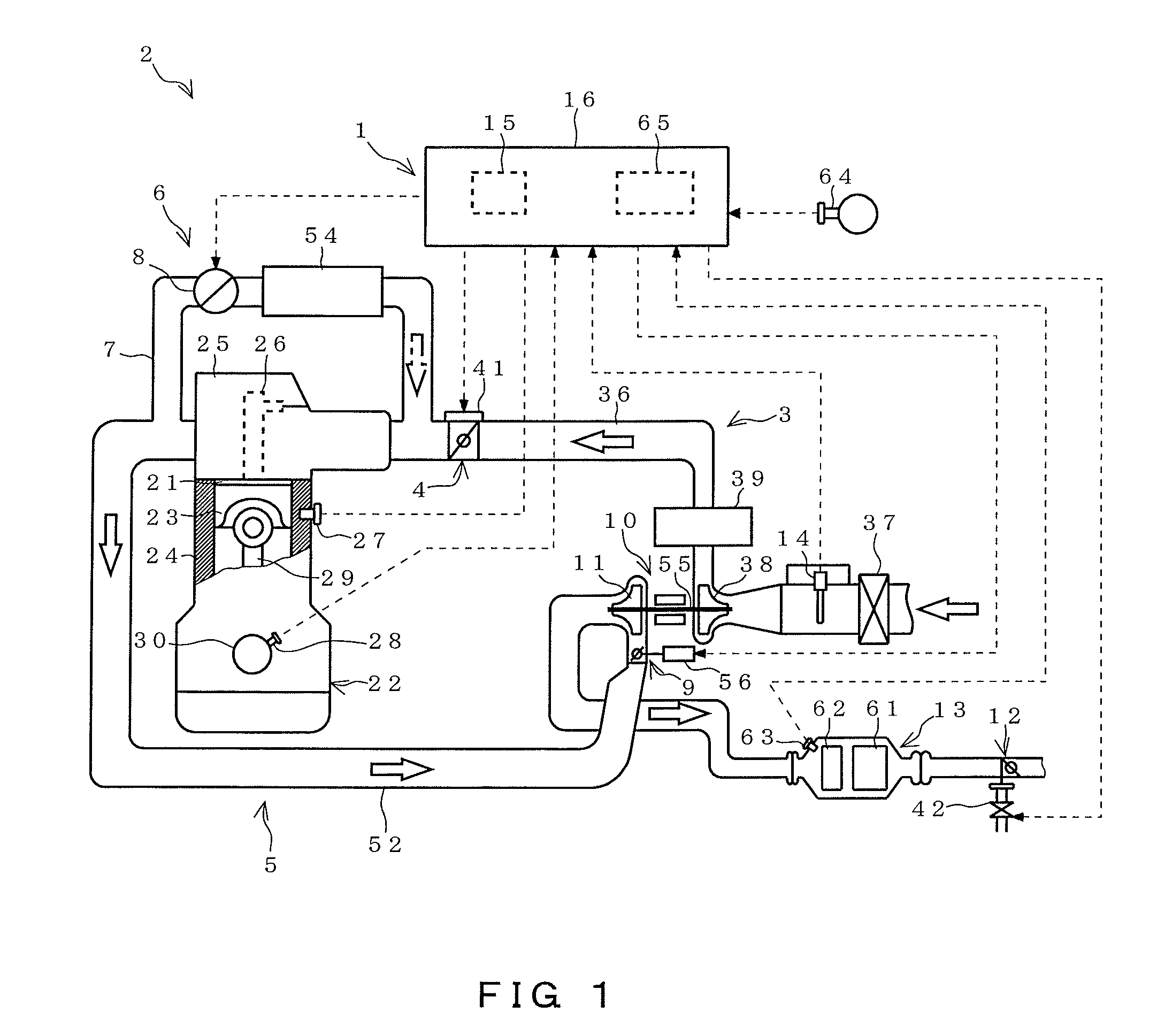
[0027]The general structure of an engine in which the diagnosing device of this embodiment has application will be described with reference to FIG. 1.

[0028]As shown in FIG. 1, an engine 2 comprises an engine main body 22 in which a combustion chamber 21 is formed, an intake passage 3 for supplying intake air (air) to the engine main body 22, an exhaust passage 5 for discharging exhaust gas from the engine main body 22, a turbocharger 10 for pressurizing the intake air to the engine main body 22, an...


PUM


Abstract

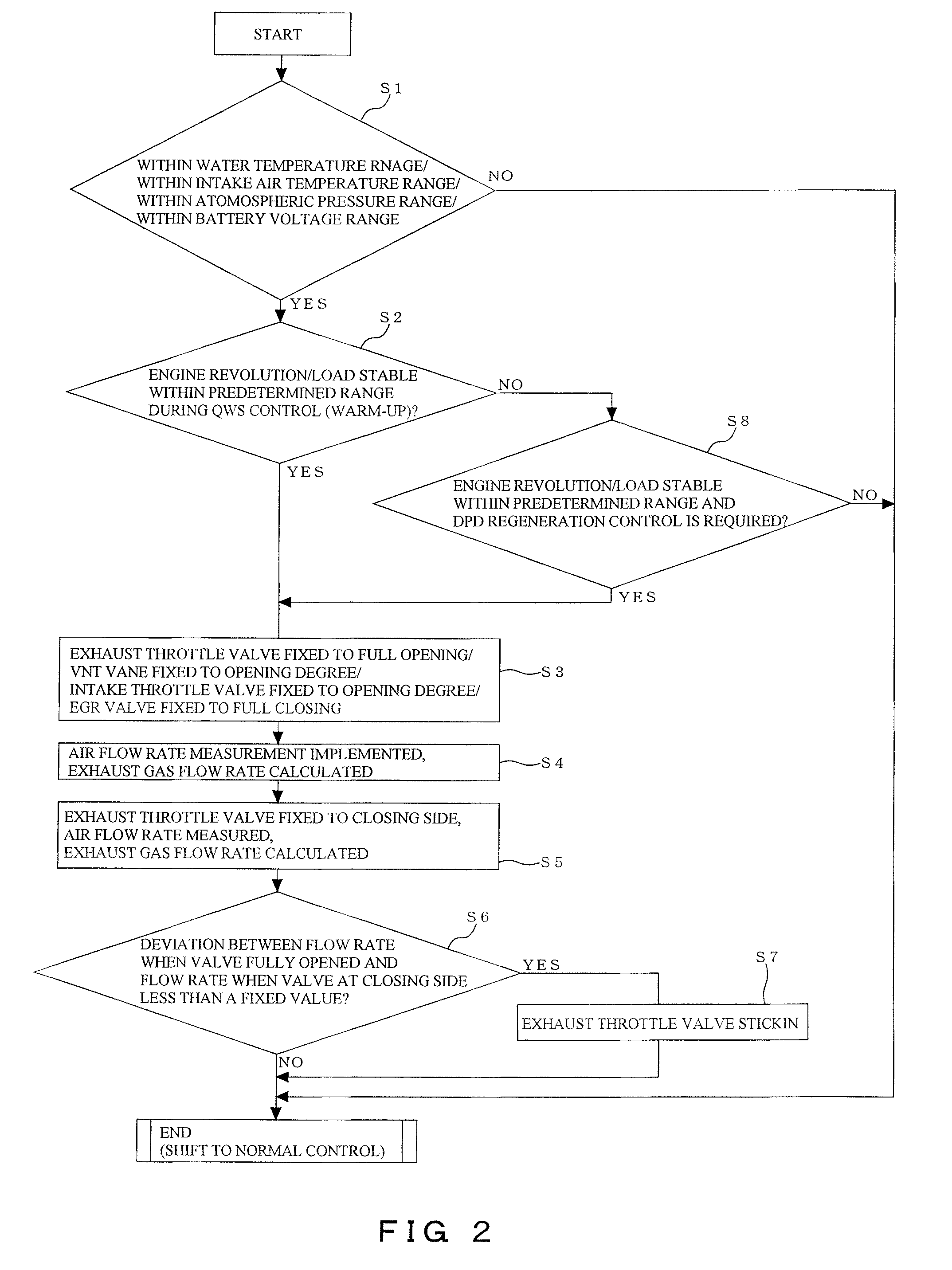
When switching an exhaust throttle valve from full opening to a closed position to warm up an engine, an intake throttle valve is fixed to full opening, an EGR valve is fixed to full closing, and a variable turbo-vane is fixed to a predetermined opening degree to accelerate a gas flow rate from an intake passage to an exhaust passage, a fully opened flow rate is detected and stored by gas flow rate detection means, with the exhaust throttle valve being full opening, after which an instruction is issued to the exhaust throttle valve to switch from the full opening to a closed position for detecting a closed position flow rate, a flow rate difference is determined by deducting the detected closed position flow rate from the stored fully opened flow rate, and failure of the exhaust throttle valve is judged when the flow rate difference is less than a predetermined threshold value.

Description

CROSS REFERENCE TO RELATED APPLICATION [0001]This application claims priority to Japanese Patent Application No. 2007-53042 (filed Mar. 2, 2007), the details of which are incorporated herein by reference.BACKGROUND OF THE INVENTION[0002]1. Field of the Invention[0003]The present invention relates to a an exhaust throttle valve diagnosing device and method for diagnosing mechanical failure of an exhaust throttle valve provided in an exhaust passage of an engine.[0004]2. Description of the Related Art[0005]Exhaust throttle valves for throttling the exhaust of an exhaust passage are be fitted to, for example, the diesel engines of large automotive vehicles (see, for example, Japanese Unexamined Patent Application No. H11-148375).[0006]Such exhaust throttle valves are controlled to throttle the exhaust when, for example, engine warm-up and exhaust purifying filter device (DPD device) regeneration are implemented. More specifically, when a control computer of the engine judges that eithe...

Claims


Application Information

Patent Timeline
Patent Type & Authority Applications(United States)
IPC IPC(8): F01N11/00
CPCF01N3/035Y02T10/144F02B39/16F02B2275/14F02D9/04F02D41/0007F02D41/0055F02D41/029F02D41/068F02D41/18F02D41/221F02M25/0707F02M25/0713F02M25/0727F02B37/22F02M26/05F02M26/10F02M26/23Y02T10/12
Inventor HANARI, AKIRAYOMOGIDA, KOUICHIROU
Owner ISUZU MOTORS LTD
Learn More