Storing, transporting and handling compressed fluids

a technology of compressed fluid and storage container, which is applied in the direction of liquid transfer device, container discharging method, manufacturing tools, etc., can solve the problems of high cost, limited effective strength of materials used to fabricate these essentially rigid containers, and high cost of steel cylinder/pipeline gas storage containers discussed in prior art. , to achieve the effect of low heel

Active Publication Date: 2008-09-04
WHITE CHARLES N +1
View PDF48 Cites 47 Cited by
  • Summary
  • Abstract
  • Description
  • Claims
  • Application Information

AI Technical Summary

Benefits of technology

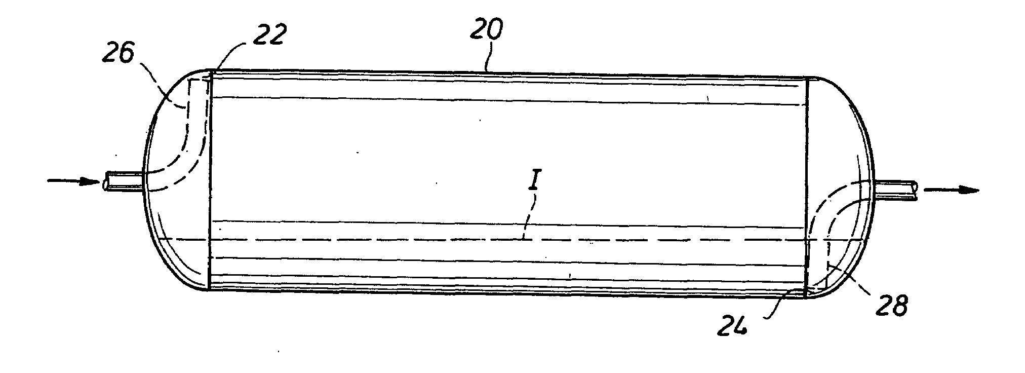
[0034]This inventive container is useful in a method in which the compressed fluid is charged into the membrane tank at a first location, which is transported to a second location, where it is discharged by charging the second fluid into the annular space at the second location. This method can be very good for minimizing the heel of compressed fluid remaining in the membrane tank, depending on the pressure of the second fluid and the back pressure, which is from the receiving infrastructure, on the compressed fluid. If the pressure of the second fluid is sufficiently higher than the back pressure, the amount of heel will be low. The method includes transporting the second fluid to the first location, and discharging the second fluid at the first location, where compressed fluid is charged into the membrane tank at the first location for discharging the second fluid. The method preferably includes selling the second fluid at the first location because it has commercial value at the first location. For example, the compressed fluid may be natural gas, and the second fluid may be carbon dioxide. Either of the fluids could be inside the membrane tank as opposed to inside the annular space.
[0035]In charging either the membrane tank or the annular space with compressed natural gas, there is a Joules-Thompson effect that cools the gas due to expansion of the gas. The cooling can cause liquid droplets to form and fall out, and it is preferred to maintain the gas in a dense gaseous phase. It is preferred to maintain a desired pressure in the annular space while charging the compressed fluid in the membrane tank so that the temperature of the compressed fluid is maintained within a desired range.

Problems solved by technology

Gases are presently stored in relatively long cylinders, bullet tanks, oblate spheroids or spheres that all feature at least one circular cross-section cut and have relatively high wall thickness to diameter ratios (t / D) to resist pressure-induced hoop stresses because the materials used to fabricate these essentially rigid containers are of limited effective strength in the orientation of the critical stresses (regardless whether metallic or fiber-based matrix shells or hybrid composites thereof).
However, steel cylinders / pipeline gas storage containers discussed in prior art are relatively heavy as compared to the weight of the gas cargo contained.
When the gas is to be transported (e.g., by truck, rail, barge, or ship), it is important to optimize the weight of the gas cargo to the weight of the containment because high containment weight generally means higher costs and limitations on how many containers can be placed in or on conveyances of limited load capacity (e.g., trucks on highways).
However, such a container is still expected to be an essentially rigid cylinder and the premise is little different than just laying a long loop of a large diameter pipeline deep undersea for storage.
The composite wall cylinders have proved to be successful strategies for improving the gas / container weight ratio, but they have also proven to be a substantially more costly solution as compared to the simple metal cylindrical bottle (or pipeline) for storage of gas at a given pressure.
The heavy cylindrical containers are costly to support and transport whether being carried in or on land vehicles or marine vessels.
Except for lined carbon fiber composite tanks, moderate and high pressure gas cargo tanks as currently in practice or as cited in prior art exhibit relatively high self weights that impose practical constraints on the means of transports.
Roadway load limits restrict the potential for using large diameter high pressure CNG tanks in land transport, even by rail.
Practical ship designs that recognize realistic draft limitations for port entry and dry-docking are limited in how many of the heavy cylindrical cargo containers can be carried onboard.
However, it is unlikely that a single rigid cylinder designed to withstand the high pressures typically proposed in prior art at a diameter that would match the size of the space typically available within the hold of a typical ship could be practically fabricated from the materials and structures proposed by prior art, whether of single or composite skin construction.

Method used


Image

  • Storing, transporting and handling compressed fluids
  • Storing, transporting and handling compressed fluids
  • Storing, transporting and handling compressed fluids

Examples


Embodiment Construction

[0067]Storing and Transporting Natural Gas

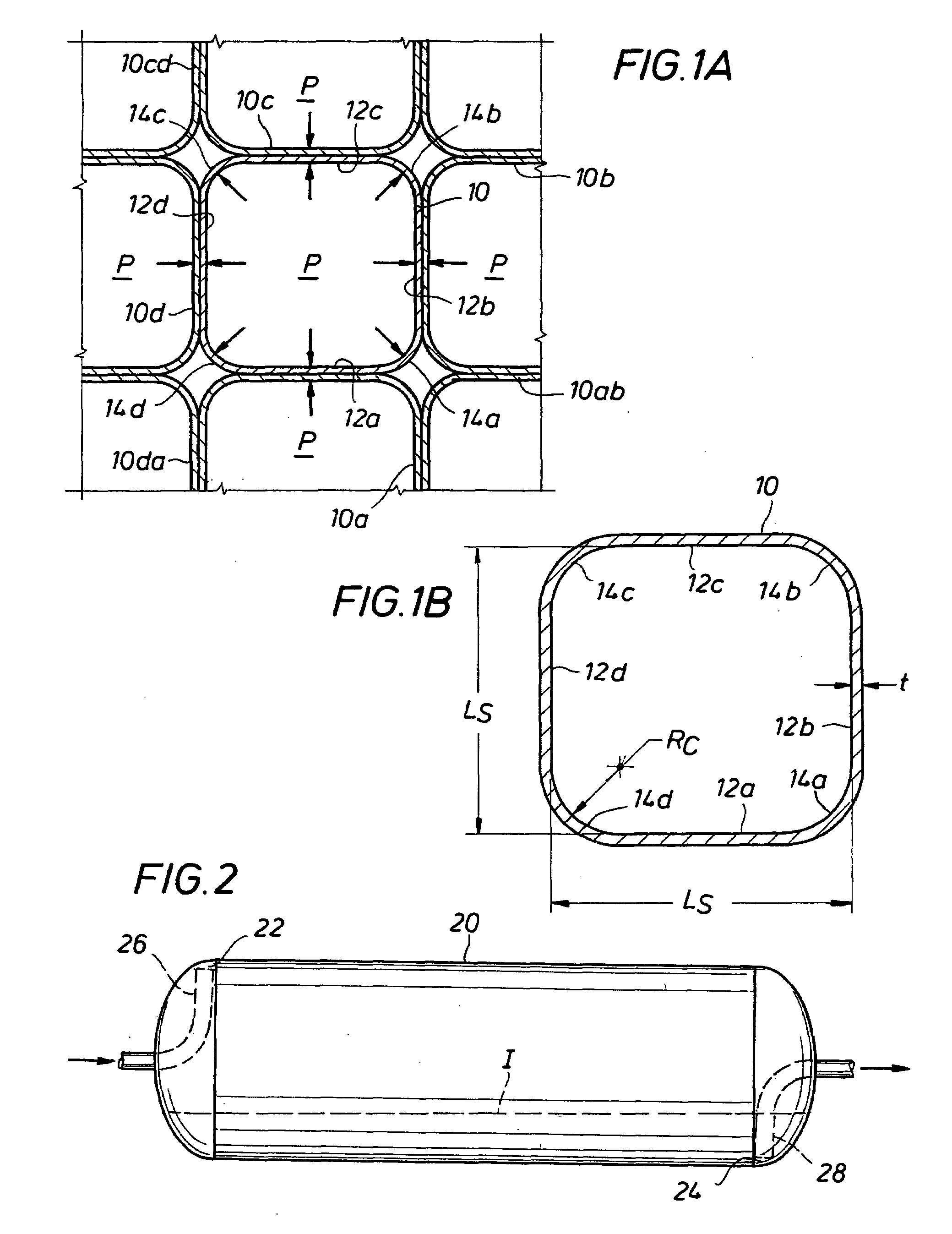
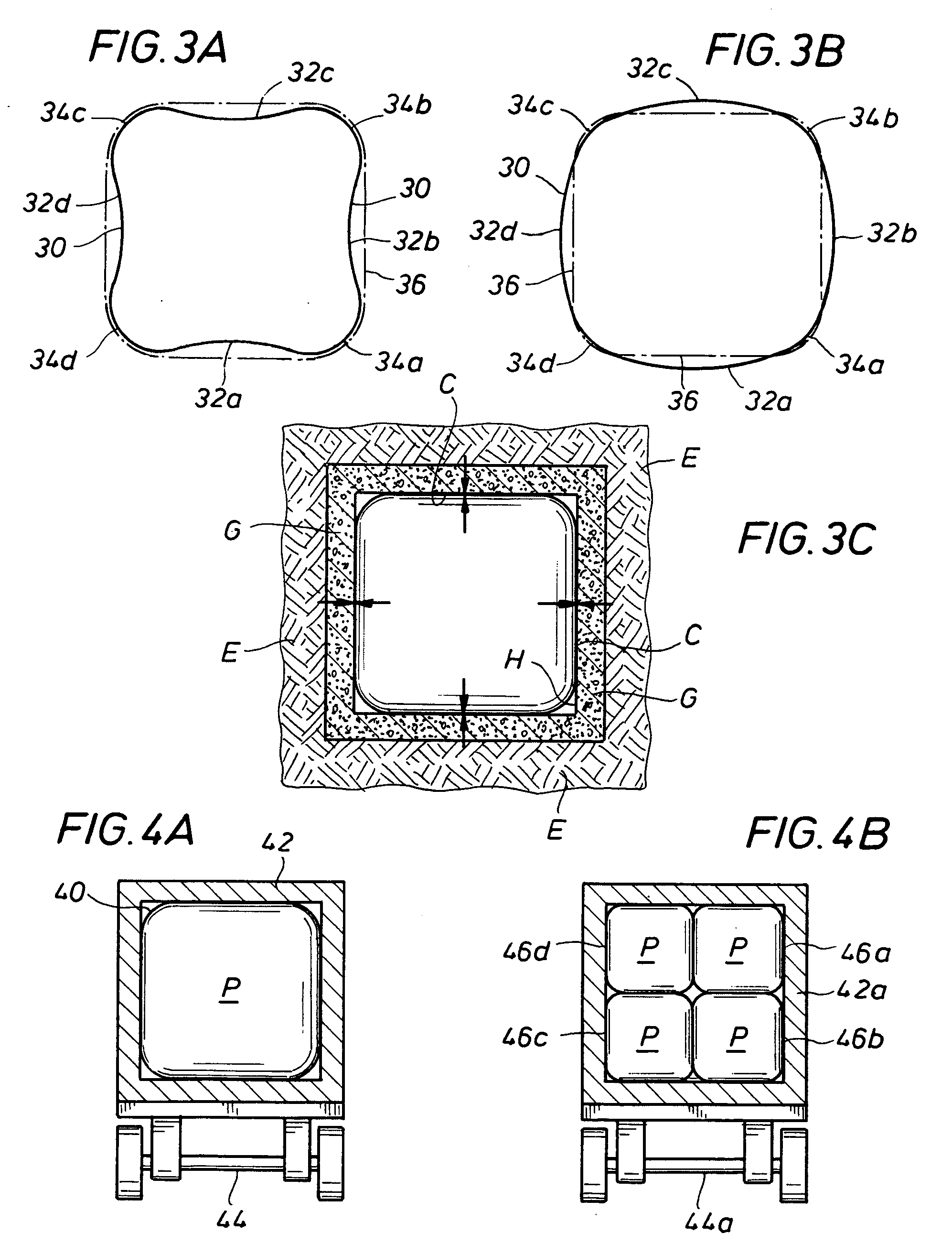
[0068]The present invention provides innovative forms of containment for storage and / or transport of fluids, such as natural gas and / or natural gas liquids, as well as innovative means for loading to and discharging from stationary or transportable cargo containers. Highly efficient cargo container design and utilization of available cargo hold spaces within the means of transport can be achieved with the present invention. Cargo containers according to the present invention rely on external support to complement the structural capacity of the container itself. Cargo fluids are stored at very low temperatures and low-to-moderate pressures within the cargo containers. The cargo containers are designed to have polygonal bodies and are shaped such that their structural capacity to contain cold, pressurized cargo fluid normally depends on the support of adjacent containers and / or on the support of walls that define a cargo hold space.

[0069]A car...


PUM

PropertyMeasurementUnit
temperatureaaaaaaaaaa
pressureaaaaaaaaaa
atmospheric pressureaaaaaaaaaa

Abstract

A container and a method for storage and / or transport of a compressed fluid such as compressed natural gas are provided. The container has a pair of opposing heads and a wall section between the heads, the wall section defining a square cross-section comprising substantially planar sides joined together by rounded corners. The container is designed for the side walls to deflect outwardly while under pressure, but to be supported externally by a support system that restricts outward expansion of the side walls. The support system can be provided as the walls of a cargo hold in a marine or land transport vessel, an ISO shipping container or an underground shaft. Multiple containers can be located side by side in the external support system so that the sides of adjacent containers rest against each other for support while under pressure. In one embodiment, a container comprises an outside tank and a flexible membrane tank inside the outside tank, an annular space being defined in between, where a first fluid is charged into the membrane tank and a second fluid is charged into the annular space in order to discharge the first fluid. In another embodiment, a long tube having a square cross-section is coiled in a support structure and made gas-tight for holding a compressed fluid. The walls of the tube would tend to expand while under pressure, but adjacent coils and the support structure limit the expansion.

Description

CROSS REFERENCE TO RELATED APPLICATION[0001]Priority is claimed to U.S. Provisional Patent Application Ser. Nos. 60 / 904,541 and 60 / 926,504, each of which was filed by the present inventor on Mar. 2, 2007, and Apr. 27, 2007, respectively, and each is incorporated by reference. A U.S. patent application filed by the present inventor on a date concurrent herewith, which claims priority to the same provisional patent applications, entitled “Apparatus and Method for Flowing Compressed Fluids Into and Out of Containment” is related hereto and incorporated by reference.BACKGROUND OF THE INVENTION[0002]1. Field of the Invention[0003]This present invention pertains to the storage and transport of gas and liquids, and more particularly to storage and / or transport of refrigerated and pressurized fluid cargos (e.g., natural gas and natural gas liquids) in relatively thin-walled containers at low temperatures where commercial cargo densities can be achieved at moderate pressures and where the co...

Claims


Application Information

Patent Timeline
Patent Type & Authority Applications(United States)
IPC IPC(8): F17C7/02B21D39/03B67D99/00
CPCF17C2201/0104F17C2227/0339F17C2205/0176F17C2223/033F17C2227/0388F17C2227/0341F17C2227/0192F17C2205/0111F17C13/026F17C2205/0146F17C2227/0157F17C2201/054F17C2223/043F17C2270/01F17C2225/0123F17C2225/0153F17C2227/0372F17C2250/0631F17C2225/046F17C2227/043F17C2223/046F17C2225/0115F17C2225/033F17C2223/0123F17C2221/011F17C2270/0105F17C2221/012F17C2221/031F17C2223/0153F17C2201/032F17C7/00F17C13/025F17C2221/014Y10T29/49826F17C2221/033F17C5/02F17C7/02F17C5/06F17C2201/052F17C2265/022F17C2221/035Y02E60/321F17C2205/013F17C2223/0115F17C2225/035F17C2250/0626F17C2205/0142F17C2227/048F17C2227/0337F17C2270/0134Y02E60/32Y10T137/0324F17C13/04
Inventor WHITE, CHARLES N.
Owner WHITE CHARLES N
Why Eureka
Try Eureka