
Fast-Releasing Device Of Actuator

a technology of actuator and fast release, which is applied in the direction of mechanical equipment, tables, etc., can solve the problems of internal components corrosion, still some drawbacks of the conventional fast release device of the actuator, and the operation is less smooth, so as to improve the dust-proof, waterproof and moisture-proof effect of the casing, and simplify the assembly process. effect of the activator

Active Publication Date: 2008-09-04
TIMOTION TECH CO LTD
View PDF5 Cites 48 Cited by
  • Summary
  • Abstract
  • Description
  • Claims
  • Application Information

AI Technical Summary

Benefits of technology

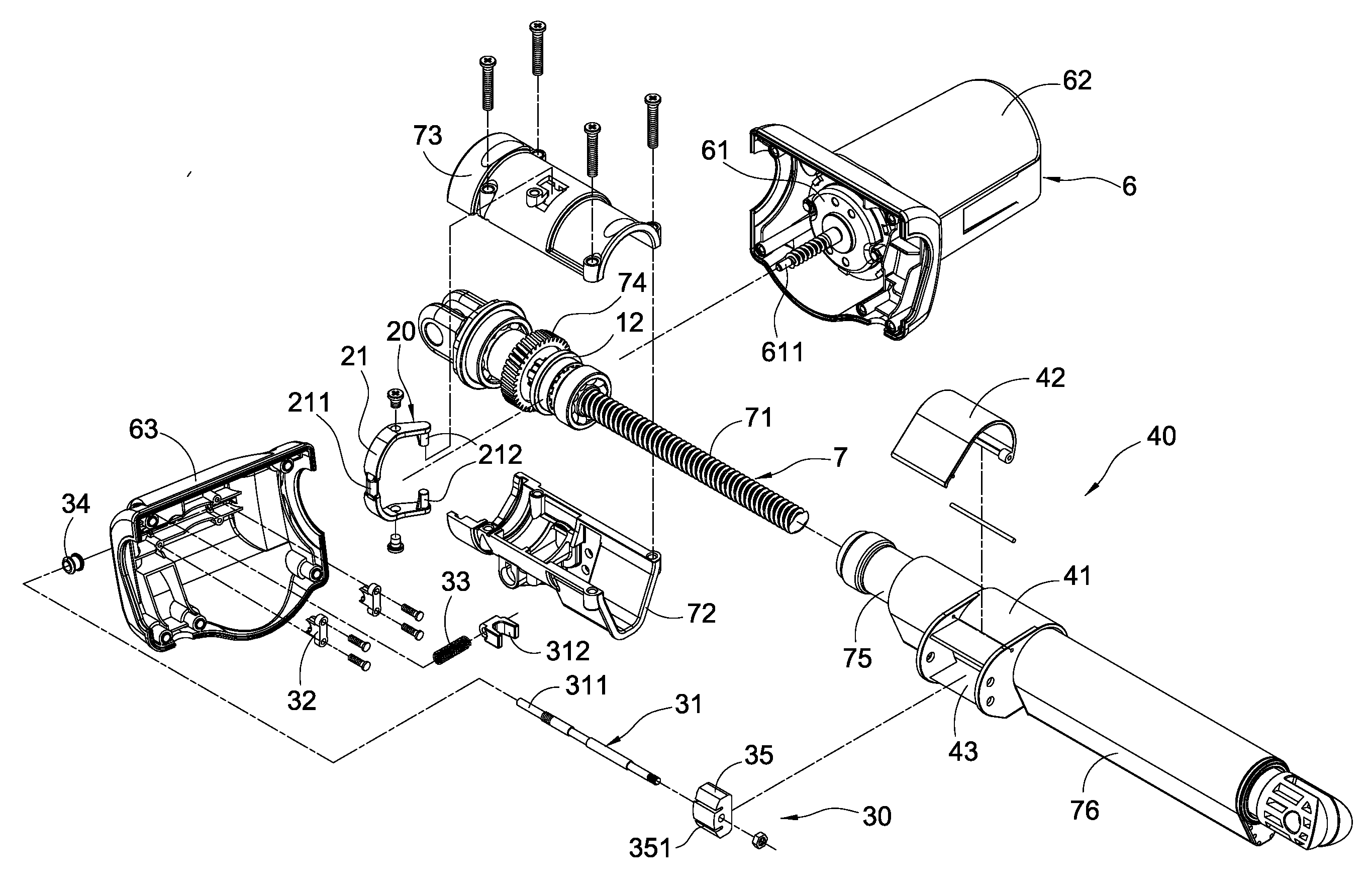
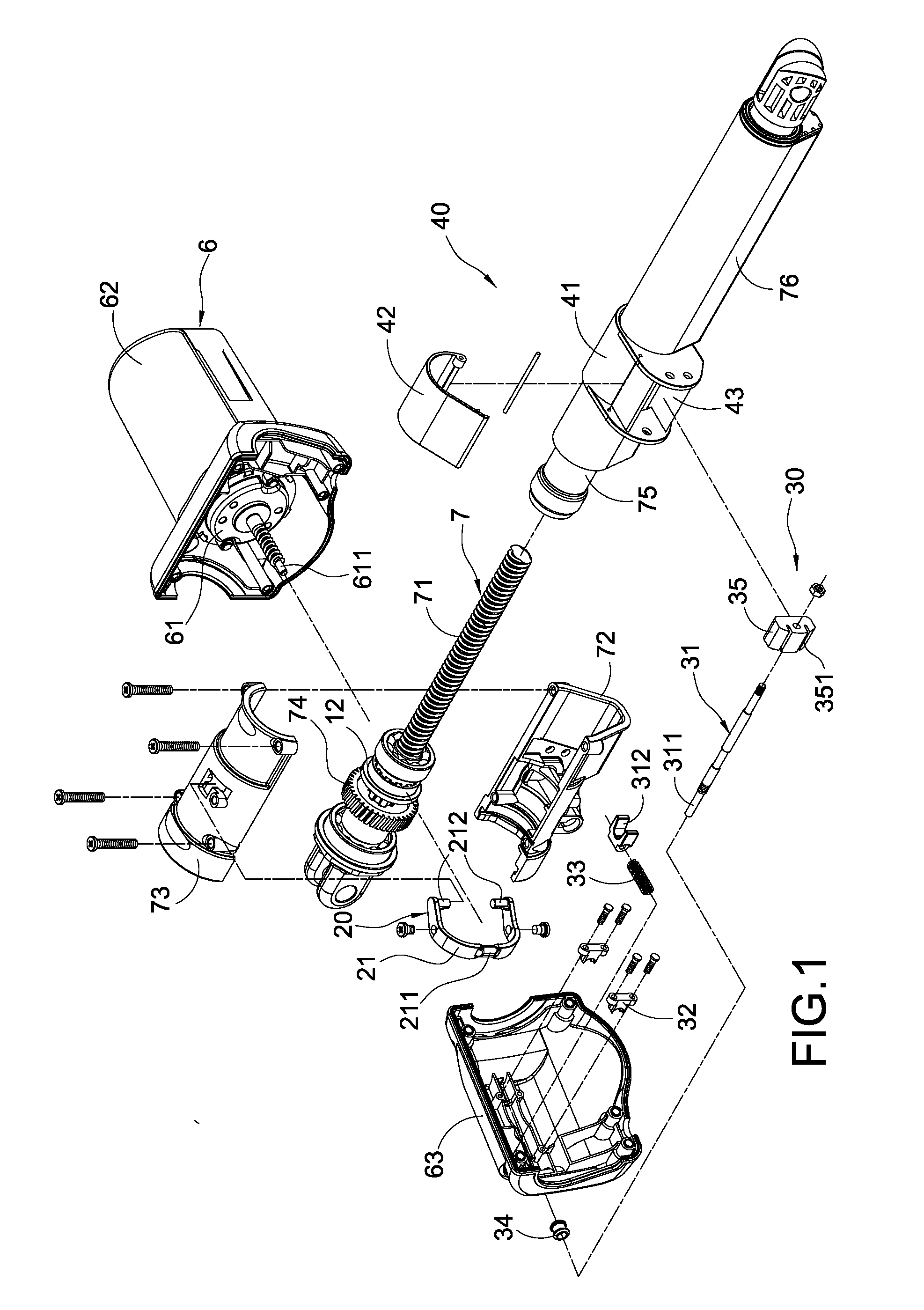
[0007]The present invention is to provide a fast-releasing device of an activator, in which a pulling rod assembly is connected to a swinging arm to transfer the curved swinging movement into a linear displacement, thereby to substantially reduce the tension force applied to the cable by an operator.
[0009]According to another aspect, the present invention is to provide a fast-releasing device of an activator, in which the pulling means is first fixedly connected within an upper casing, and then the upper casing covers on a lower casing, thereby to substantially simplify the process of assembling the activator and reduce the time for assembling.
[0010]According to another aspect, the present invention is to provide a fast-releasing device of an activator. With the integrally sealed manufacture of the upper and lower casings, waterproof gaskets are provided between the upper casing and the pulling rod, thereby to generate a better dust-proof, waterproof and moisture-proof effect within the casing.

Problems solved by technology

Therefore, it is an important issue for those skilled in this art to develop such fast-releasing device of an actuator.
However, when in use, there are still some drawbacks existing in the conventional fast-releasing device of an actuator.
As a result, the applied force should be larger, causing the operation less smoothly.
Thus, moist or dust often penetrates into the base, causing the corrosion of the internal components and in turn the substantial reduction in lifetime.

Method used


Image

  • Fast-Releasing Device Of Actuator
  • Fast-Releasing Device Of Actuator
  • Fast-Releasing Device Of Actuator

Examples


Embodiment Construction

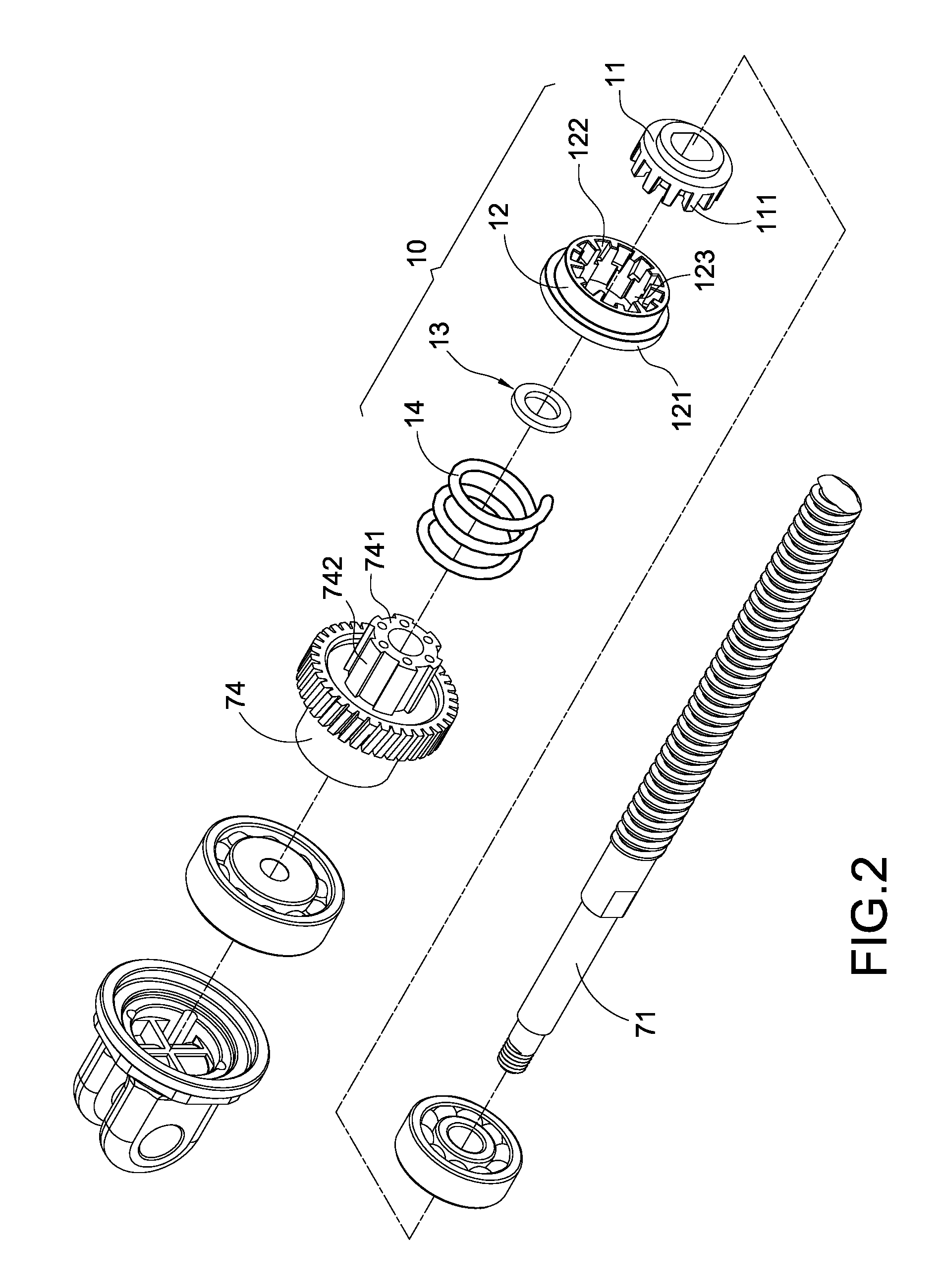
[0018]The detailed description and the technical contents of the present invention will be explained with reference to the accompanying drawings. However, it should be understood that the drawings are illustrative only but not to limit the present invention thereto. FIG. 1 is an exploded perspective view of the activator of the present invention. FIG. 2 is an exploded perspective view of the clutching means and the transmission means of the present invention. FIG. 3 is an exploded perspective view of the pulling means and the casing of the present invention. FIG. 4 is a schematic view showing the assembly of the activator of the present invention. The present invention provides a fast-releasing device of an activator. The activator has a motor means 6 and a transmission means 7. The motor means 6 comprises a motor 61, a lower casing 62 covering the outside of the motor 61, and an upper casing 63 correspondingly covering over the lower casing 62. A worm 611 projects from the center o...


PUM


Abstract

A fast-releasing device of an activator includes a clutching means, a turning means and a pulling means. The clutching means covers on a screw rod of the activator and is accommodated within a base, and includes a fixing base and a clutch. The turning means is accommodated within the casing of the activator and includes a swinging arm pivoted to the base. One end of the swinging arm is arranged to correspond to the clutch so as to control the clutching action between the fixing base and the clutch. The pulling means includes a pulling rod assembly. One end of the pulling rod assembly is accommodated within the casing and connected to the swinging arm, and the other end thereof penetrates out of the casing and is joined with a connecting block. With the above arrangement, a curved swinging movement can be transferred into a linear displacement, thereby to substantially reduce the applied tension force of an operator.

Description

BACKGROUND OF THE INVENTION[0001]1. Field of the Invention[0002]The present invention relates to a fast-releasing device, and in particular to a fast-releasing device of an actuator suitable for an electric sickbed.[0003]2. Description of Prior Art[0004]It is well known that actuators can be widely used in electric sickbeds, treadmills, and wheelchairs for adjusting or changing the positions or inclination thereof. When a patient is subjected to an emergent medical treatment, a fast-releasing device capable of generating a fast-releasing action on the actuator can rapidly change and adjust the position of the sickbed, thereby to strive for the most important time for rescuing the patient. Therefore, it is an important issue for those skilled in this art to develop such fast-releasing device of an actuator. Taiwan Patent Publication No.M275836 discloses a conventional fast-releasing device of an actuator. The actuator comprises a motor means and a transmission means. The motor means ...

Claims


Application Information

Patent Timeline
IPC IPC(8): F16H3/08
CPCF16H1/16F16H25/20F16H2025/2071F16H2025/2084Y10T74/18704F16H2025/2031Y10T74/18688Y10T74/18696F16H2025/209
Inventor WANG, CHIA-JUNG
Owner TIMOTION TECH CO LTD
Learn More