Liquified Natural Gas Sump For a Gravity Based Structure

a gravity-based structure and liquefied natural gas technology, applied in the field of liquefied natural gas (lng) sumps, can solve the problems of not disclosing an lng sump, the problem of dealing with lng spills in a gbs environment is a new issue, and the patent does not disclose an lng sump, so as to minimize the evolution rate of gaseous methane and small surface area

Inactive Publication Date: 2008-09-04
IHI E&C INT
View PDF32 Cites 5 Cited by
  • Summary
  • Abstract
  • Description
  • Claims
  • Application Information

AI Technical Summary

Benefits of technology

[0020]According to an embodiment of the present invention, a sump includes a preferably long, relatively narrow cylindrical structure that provides sufficient LNG spill containment while minimizing the rate of evolution of gaseous methane at the surface due to the relatively small surface area. The cylinder can be insulated and is preferably arranged to fit neatly into a GBS compartment. Spills from a loading platform can enter the sump area through a trough through the GBS wall.

Problems solved by technology

Since LNG has never before been stored in a GBS, dealing with LNG spills in a GBS environment is a new issue.
The patent does not disclose an LNG sump.
The patent does not disclose of an LNG sump.
This patent also does not disclose of an LNG sump.

Method used


Image

  • Liquified Natural Gas Sump For a Gravity Based Structure
  • Liquified Natural Gas Sump For a Gravity Based Structure
  • Liquified Natural Gas Sump For a Gravity Based Structure

Examples


Embodiment Construction

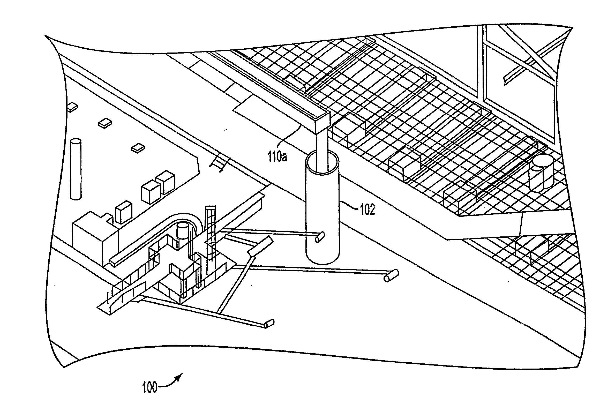
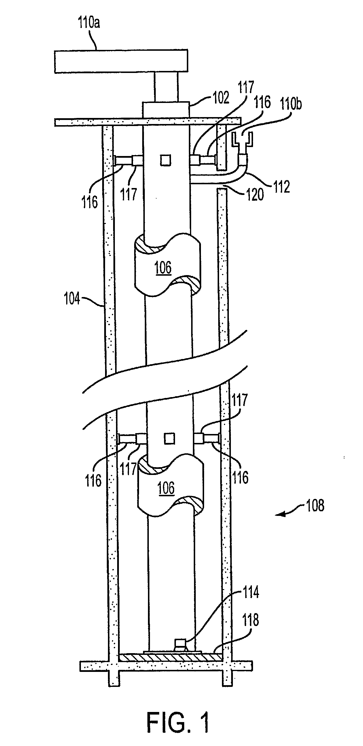
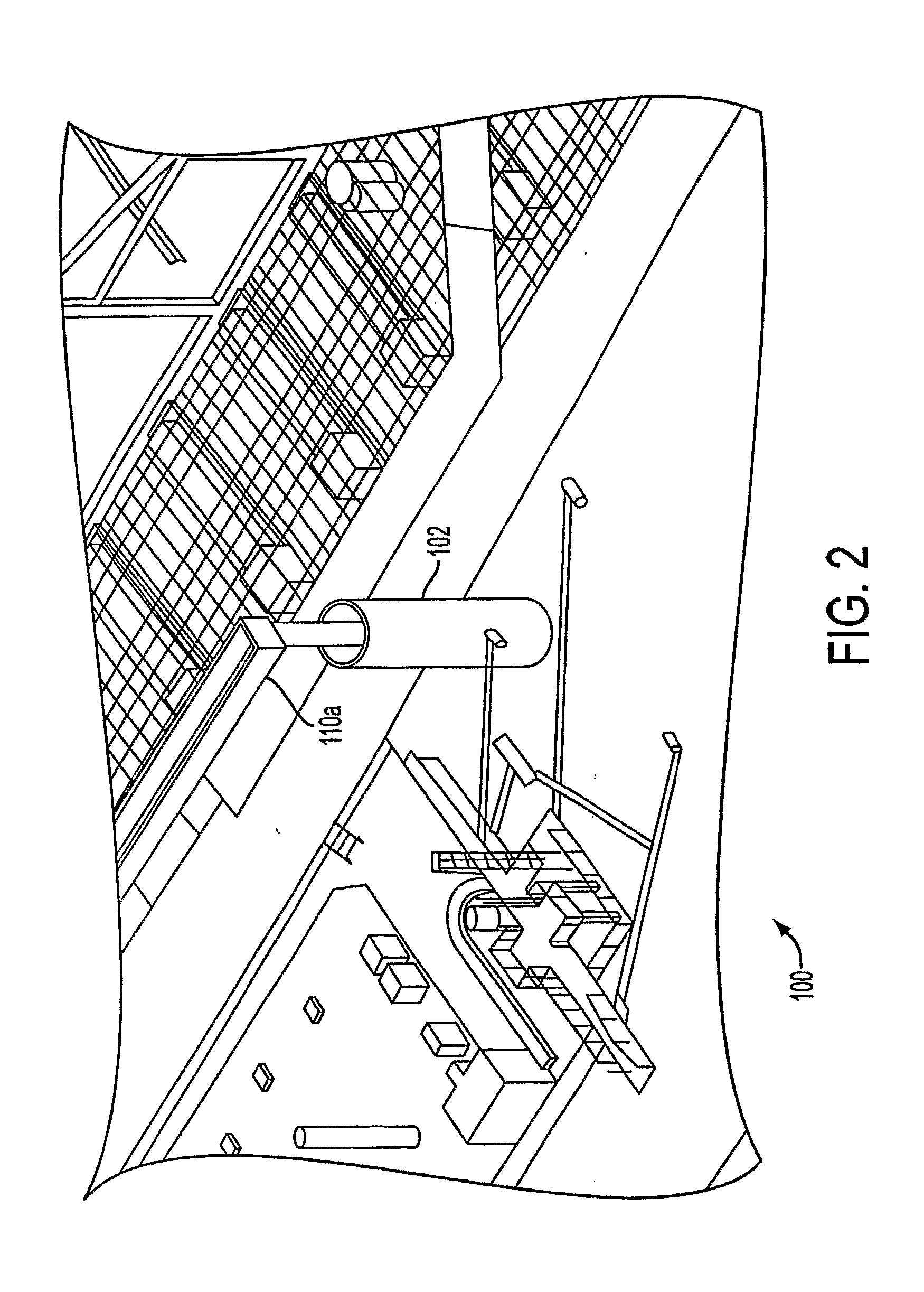
[0030]As shown in FIG. 1, an LNG sump 102 has a long relatively narrow cylindrical shape, which has the effect of providing sufficient LNG spill containment while minimizing the rate of evolution of gaseous methane at the surface due to the relatively small surface area. The cylinder may be insulated (106, not shown as completely covering sump) and should fit neatly into a GBS compartment 104. Electrical heat tracing, such provided by a heat blanket 108, can be provided on the outside of the LNG sump 102 and used to protect the surrounding concrete from cryogenic temperatures while allowing some control over the rate of vapor evolution. The electrical tracing or heat blanket fitted outside of the insulation.

[0031]A trough 110a collects spilled LNG from the process area and delivers it to the LNG sump 102. A second trough 110b can be used to collect spilled LNG from a jetty or the like, and delivers the spilled LNG to the LNG sump 102 via separate inlet 112 through a slot 120 in the ...


PUM


Abstract

A liquefied natural gas (LNG) sump is provided for a gravity based structure (GBS). The sump includes a sump containment structure having a predetermined volume and floor surface area. The volume and floor surface area are selected in order to allow spilled LNG contained within the sump containment structure to vaporize at a predetermined, safe rate. A trough is provided for collecting spilled LNG on the GBS, such as at the processing area and on a jetty, and delivering the spilled LNG to the sump containment structure.

Description

RELATED APPLICATION DATA[0001]This application claims the benefit pursuant 35 U.S.C. §119 of the filing date of U.S. provisional patent application No. 60 / 611,388, filed Sep. 21, 2004, the entire contents of which are hereby incorporated by reference.BACKGROUND OF THE INVENTION[0002]1. Field of the Invention[0003]The present invention relates generally to sumps and, more particularly, to a liquefied natural gas (LNG) sump for containment of LNG spills on an offshore gravity based structure or other offshore installation.[0004]2. Description of the Related Art[0005]Gravity based structures (GBS) have been used in the design of offshore oil and gas storage facilities for more than 30 years in many parts of the world, predominantly in areas of severe storms for years to design. Due to their strength and reliability, gravity-based structures have been such as the North Sea offshore Norway and Scotland, and in an area offshore Newfoundland where energy operators must contend with floatin...

Claims


Application Information

Patent Timeline
IPC IPC(8): F17C13/00B65D90/24
CPCC10L3/10F17C2203/03F17C2203/0646F17C2203/0678F17C2270/0121F17C2221/033F17C2223/0161F17C2223/033F17C2250/0605F17C2205/0119Y10T137/0318Y10T137/5762
Inventor KOLODZIEJ, EDWINMILLS, JOHN A.ADAMS-SMITH, JENNIFER C.
Owner IHI E&C INT
Why Eureka
Try Eureka