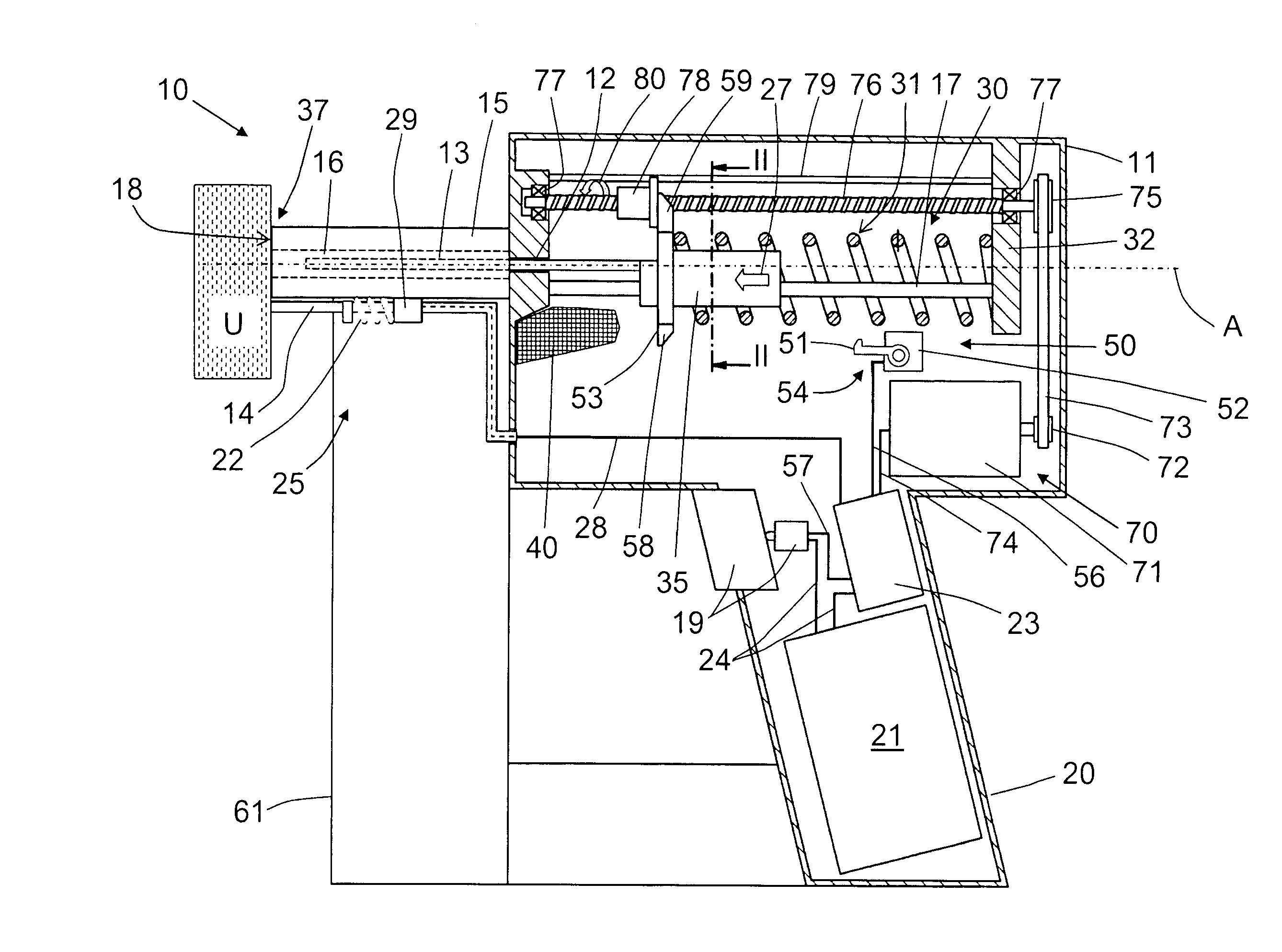
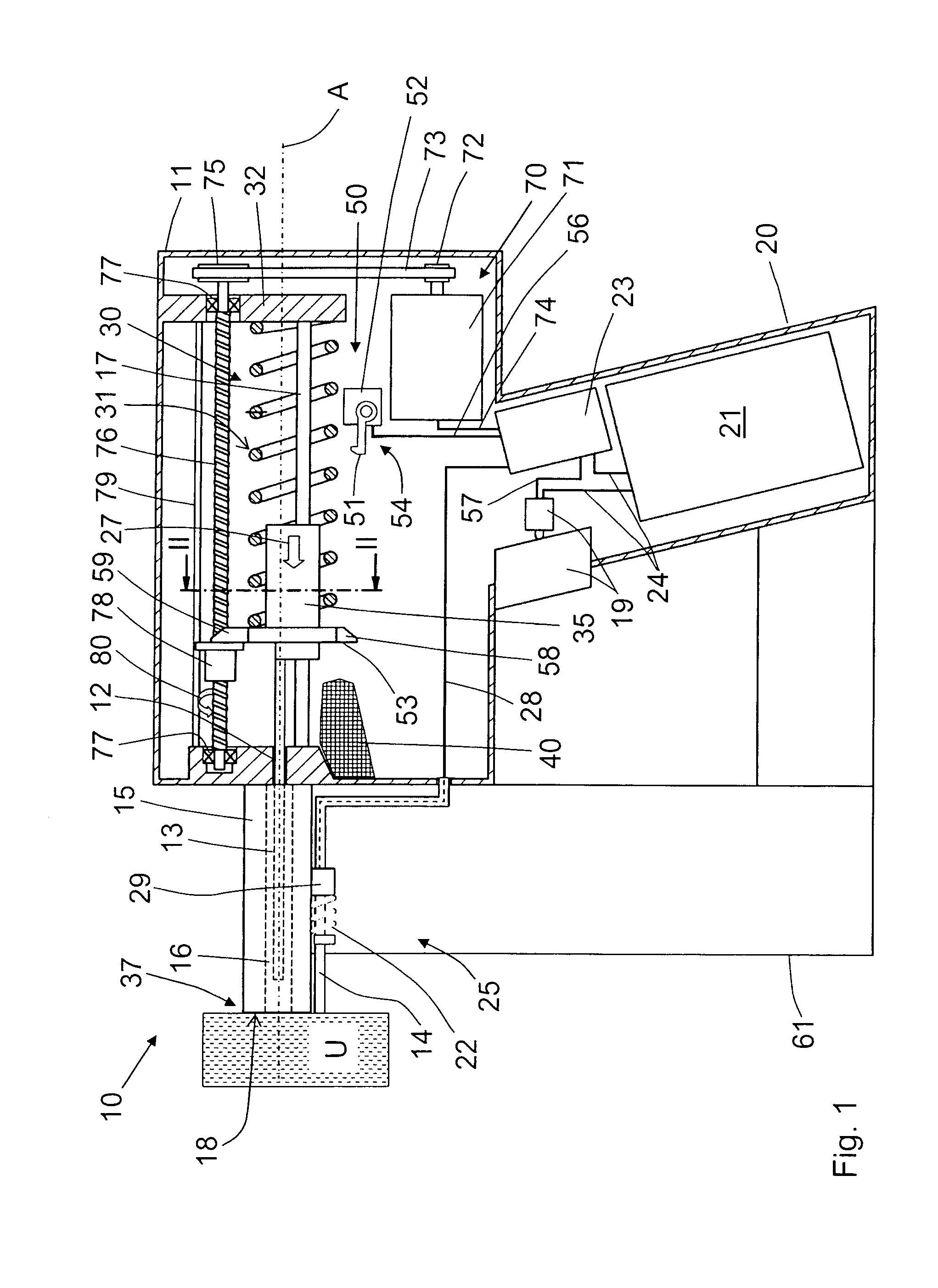
[0010]This and other objects of the present invention, which will become apparent hereinafter, are achieved by providing in a drive-in tool of the type discussed above, a sliding nut supported on the threaded spindle without a possibility of rotation thereabout but with a possibility of an
axial displacement therealong, with the sliding nut being axially displaceable, upon actuation of the motor of the tensioning device by a
control unit of the drive-in tool, between a first end position and a second end position and being displaceable, during a loading cycle, from the first end position to a second end position for displacing the driving spring into the loading position of the driving spring, and being subsequently displaceable from the second end position thereof into the first end position to provide for displacement of the driving spring into its release position. Thereby, the sliding nut is again in its initial position before a drive-in process is initiated, and the path for the driving spring is free. In case, the driving spring is loaded indirectly, via the drive-in ram, when the sliding nut cooperates with the drive-in ram, the drive-in ram can likewise be displaced to its initial position with the displacement of the sliding nut to its initial position. A complicated
mechanics for the return displacement of threaded spindle is not any more necessary. Likewise, the problem of a chipped edge of the thread of the threaded spindle is eliminated.
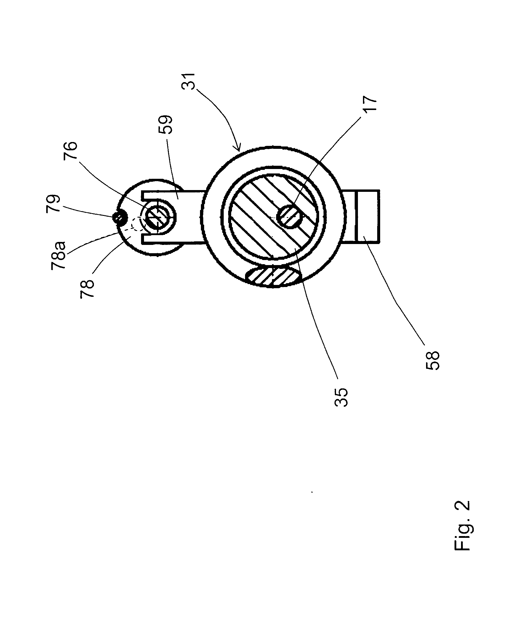
[0011]It is advantageous, when the sliding nut is provided with at least one ball that serves as thread engagement means for engaging the threaded spindle. With formation of the sliding nut as a ball nut, the frictional and energy losses, which occur during displacement of the drive-in ram against the driving spring, can be noticeably reduced.
[0012]It is further advantageous when a first control conductor connects the locking device with the
control unit, and a second control conductor connects the motor of the tensioning device with the control unit. Thereby, it becomes possible, to use the locking device for controlling reversing of the direction of rotation of the motor of the tensioning device in order to effect displacement of the sliding nut to its first, initial end position, e.g., when the pawl of the locking device engages, at the end of the loading movement of the tensioning device, the locking surface on the drive-in ram, generating a
control signal. Alternatively, the reversing of the rotational direction of the motor can take place when the
motor load reaches a predetermined value, e.g., when the driving spring (and also the drive-in ram, as the case may be) reaches its loaded position.
[0013]A technically simple solution of retention of the sliding nut against rotation is achieved by providing a guide element along which the sliding nut can be displaced without a possibility of rotation.
[0014]Advantageously, there is provided at least one damping member for braking movement of the drive-in ram in a drive-in direction, which is spaced from a first stop of the drive-in ram, with which the damping member cooperates, by an
axial distance that is smaller than an
axial distance by which the sliding nut is spaced, in its first end position from a stop of the drive-in ram which is located opposite the sliding nut. Thereby, an
impact of the drive-in ram, which is displaceable in the drive-in direction, on the sliding nut that occupies its first end position, at the end of the drive-in process, is prevented. The drive-in ram impacts only the damping member. This increases the service life of the sliding nut.
[0015]A compact structure is obtained when the axis of the output shaft of the motor of the tensioning device extends parallel to a
rotational axis of the threaded spindle, and the motor is located between planes defined, respectively, by end surfaces of the threaded spindle.

