Control Apparatus of Electric Power Steering Apparatus

a technology of control apparatus and electric power steering, which is applied in the direction of electric generator control, dynamo-electric converter control, dynamo-electric gear control, etc., can solve the problems of motor vibration, noise generation, sound and vibration,

Inactive Publication Date: 2008-09-04
NSK LTD +1
View PDF5 Cites 13 Cited by
  • Summary
  • Abstract
  • Description
  • Claims
  • Application Information

AI Technical Summary

Benefits of technology

[0019]Further, the object mentioned above of the present invention can be more effectively achieved by calculating the corrected q-axis current command value Iqc obtained by correcting the q-axis current command value Iqref on the basis of the rotor position θ of the motor and an angular velocity ω of the rotor, or calculating the corrected q-axis current command value Iqc obtained by correcting the q-axis current command value Iqref on the basis of the rotor position θ of the motor and the q-axis current value Iqref, or calculating the corrected q-axis current command value Iqc by adding a basic correcting current Ic previously determined by the rotor position θ to the q-axis current command value Iqref, by means of the current command value correcting means. Further, the object of the present invention can be more effectively achieved by calculating the corrected q-axis current command value Iqc by adding a compensated current value (Kw·Kd·Ic) obtained by multiplying a basic correcting current Ic previously determined by the rotor position θ by a coefficient Kw determined by the angular velocity ω of the rotor to the q-axis current command value Iqref, or calculating the corrected q-axis current command value Iqc by adding a compensated current value (Kq·Kd·Ic) obtained by multiplying a basic correcting current Ic previously determined by the rotor position θ by a coefficient Kq determined by the q-axis current command value Iqref to the q-axis current command value Iqref, by means of the current command value correcting means.

Problems solved by technology

In this case, in the motor control using the vector control mentioned above, in the case that the field-weakening control is executed at a time of the high speed rotation or the like, that is, in the case that the expression of the d-axis current command value “Idref=0” is not established, there is a problem that the motor is vibrated and a noise is generated.
Since the circulating current ic generates the torque ripple, it causes a sound and a vibration.
The countermeasures disclosed in the patent document 1 and the patent document 2 are provided for preventing the output generated by the temperature increase from being lowered, and do not improve the motion vibration and the noise mentioned above.
In the motor control using the vector control mentioned above, in the case of executing the field-weakening control at a time of the high speed rotation, that is, in the case that the expression of the d-axis current command value “Idref=0” is not established, there is a problem that the motor is vibrated so as to generate the noise.
Further, in the delta-connection type three-phase brushless motor, there is a problem that the motor is vibrated by the torque ripple caused by the circulating current ic of the motor so as to generate the noise.

Method used


Image

  • Control Apparatus of Electric Power Steering Apparatus
  • Control Apparatus of Electric Power Steering Apparatus
  • Control Apparatus of Electric Power Steering Apparatus

Examples


embodiment-1

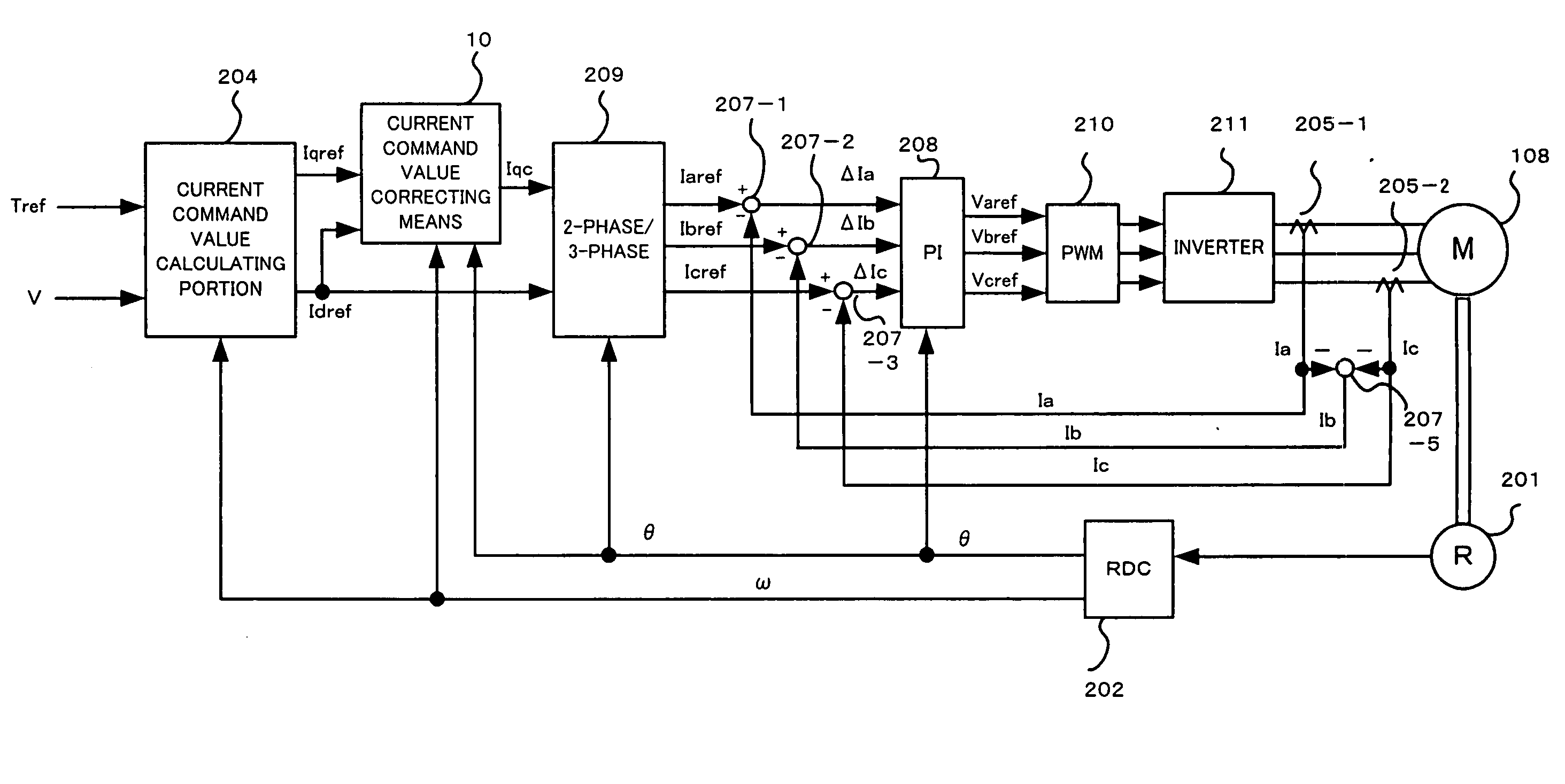
[0035]A description will be given of an embodiment 1 in accordance with the present invention with reference to FIGS. 4 and 5 on the basis of the idea mentioned above. FIG. 4 shows an entire structure of an electric power steering apparatus including a current command value correcting means 10 corresponding to a main portion of the present invention, and FIG. 5 is a block diagram showing a detail of a current command value correcting means 10 corresponding to a main portion of the present invention.

[0036]The vector control used in the present embodiment-1 is different from the conventional vector control mentioned above, and employs a control method of converting into the respective phase current command values after the d-axis current command value and the q-axis current command value are determined, and thereafter feedback controlling the motor currents in the respective phases. This vector control is called as a pseudo vector control (hereinafter, refer to as “PVC control”). In t...

embodiment-2

[0047]The embodiment-1 mentioned above is the basics of the present invention, however, the present embodiment-2 is an improvement obtained by adding an element of an angular velocity ω of the rotor to the embodiment-1. In other words, it has been known that the torque ripple generated at a time of the field-weakening control is more largely generated in accordance that the rotor turns at a higher speed. Accordingly, the corrected current (Kd·Ic) of the embodiment-1 is further regulated by the angular velocity ω.

[0048]A description will be given of the present embodiment-2 with reference to FIG. 6.

[0049]The current command value correcting means 10 is constituted by the basic correcting current calculating means 10a for outputting the basic correcting current Ic by inputting the rotor position θ, the d-axis coefficient calculating means 10b for outputting the coefficient Kd by inputting the d-axis current command value Idref, the multiplying portion 10c for multiplying by inputting ...

embodiment-3

[0052]The embodiment-1 is the basics of the present invention as mentioned above, however, the present embodiment-3 is an improvement obtained by adding an element of the q-axis current command value Iqref itself to the embodiment-1. In other words, it has been known that the torque ripple generated at a time of the field-weakening control is more largely generated in accordance that the q-axis current command value Iqref itself corresponding to the torque command value becomes larger. Accordingly, the corrected current (Kd·Ic) of the embodiment-1 is further regulated the corrected current (Kd·Ic) by the q-axis current command value Iqref.

[0053]A description will be given of the present embodiment-3 with reference to FIG. 7.

[0054]The current command value correcting means 10 is constituted by the basic correcting current calculating means 10a for outputting the basic correcting current Ic by inputting the rotor position θ, the d-axis coefficient calculating means 10b for outputting ...


PUM


Abstract

The present invention provides a control apparatus of a electric power steering apparatus which can suppress a vibration and a noise of a motor caused by a torque ripple which is generated at a tie of applying a field-weakening control to the motor or on the basis of a motor circulating current. Accordingly, the control apparatus actually measures a relation between a basic correcting current and a rotor position which can suppress the torque ripple generated at a time of applying the field-weakening control or the torque ripple based on the motor circulating current, previously, and adds a correcting current which is regulated by taking into consideration a magnitude of a weak field current of a correcting current, a magnitude of an angular velocity of the rotor or an electrical angle of the circulating current with respect to the basic correcting current, to an original current command value.

Description

TECHNICAL FIELD[0001]The present invention relates to a control apparatus of an electric power steering apparatus, and more particularly to a control apparatus of an electric power steering apparatus suppressing a torque ripple of a motor output in the case of executing a field-weakening control or on the basis of a motor circulating current.BACKGROUND ART[0002]An electric power steering apparatus applying an assist force against a steering apparatus of a motor vehicle on the basis of a rotating force of a motor is structured such that the assist force is applied to a steering shaft or a rack shaft by applying a driving force of the motor by means of a transmission mechanism such as gears, a belt or the like via a speed reduction member. A description will be given of a general structure of the electric power steering apparatus mentioned above with reference to FIG. 1.[0003]A column shaft 102 of a steering wheel 101 is coupled to a tie rod 106 of steered wheels via reduction gears 1...

Claims


Application Information

Patent Timeline
Patent Type & Authority Applications(United States)
IPC IPC(8): H02P21/00B62D5/04B62D6/00B62D103/00B62D119/00B62D137/00H02P21/05H02P21/06H02P21/22H02P23/04H02P25/026H02P27/08
CPCH02P29/0038H02P21/06H02P29/50
Inventor KOBAYASHI, HIDEYUKI
Owner NSK LTD
Why Eureka
Try Eureka