Communication terminal which perform low-delay communication by using a broadband line

a technology of broadband line and communication terminal, which is applied in the field of communication terminal, communication system, congestion control method, and congestion control program, which can solve the problems of increasing the inability to perform communication with delay shorter than the propagation delay time, and the increase of the delay time between the transmission and reception terminal. to achieve the effect of shortening the delay tim

Active Publication Date: 2008-09-04
NEC CORP
View PDF8 Cites 47 Cited by
  • Summary
  • Abstract
  • Description
  • Claims
  • Application Information

AI Technical Summary

Benefits of technology

[0014]It is a first exemplary object of the present invention to suppress a total of bandwidths of even a plurality of sessions to a bandwidth or less and to, consequently, shorten delay time between transmission and reception terminals.

Problems solved by technology

A minimum value of delay between the transmission and reception terminals is propagation delay time between the transmission and reception terminals, and communication with delay shorter than the propagation delay time may not be able to be performed.
When congestion occurs in the network, a queue to wait for a packet output is generated in a node where the congestion occurs, and delay between the transmission and reception terminals is increased by time for which the packet passes through the queue.
For this reason, the delay time between the transmission and reception terminals considerably increases by time required for packet retransmission.
However, in this method, a special device in the in-network node is required, a queueing delay still occurs when a plurality of low-delay communications are simultaneously performed.
However, these methods require special devices in in-network nodes, and cost for switching existing nodes is necessary.
A disadvantage of the first related art is that when a plurality of sessions are present, even though a limited bandwidth of each of the sessions is a bandwidth or less, a total of limited bandwidths of these sessions exceeds the bandwidth.
For this reason, when a plurality of sessions are present, a queueing delay becomes long.
A disadvantage of the second related art is that a packet having a set data amount is stationarily accumulated, and the number of accumulated packets varies to considerably vary delay time.
However, when the increase range of the transmission bandwidth is set, a large number of packets reach a network node for a short period of time.
However, time taken until congestion is communicated to a transmission terminal becomes long due to the increase in queueing delay.
As a result, the queue length becomes unstable.
Furthermore, in the first related art, the number of packets stationarily accumulated in a queue disadvantageously linearly increases depending on an increase in number of sessions.

Method used


Image

  • Communication terminal which perform low-delay communication by using a broadband line
  • Communication terminal which perform low-delay communication by using a broadband line
  • Communication terminal which perform low-delay communication by using a broadband line

Examples


first exemplary embodiment

[0070]A first exemplary embodiment of the present invention will be described below with reference to drawings.

[0071](Explanation of Configuration)

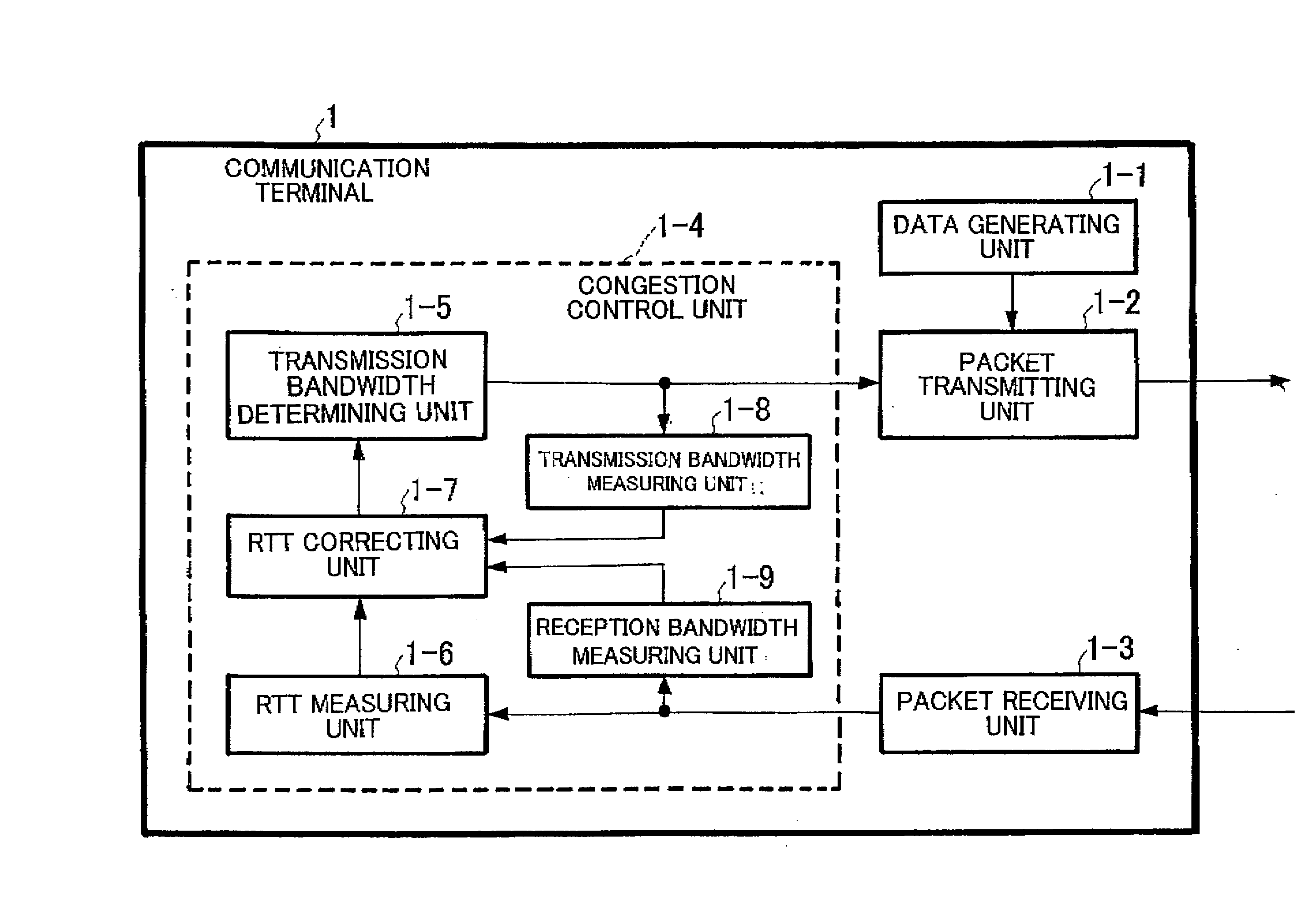
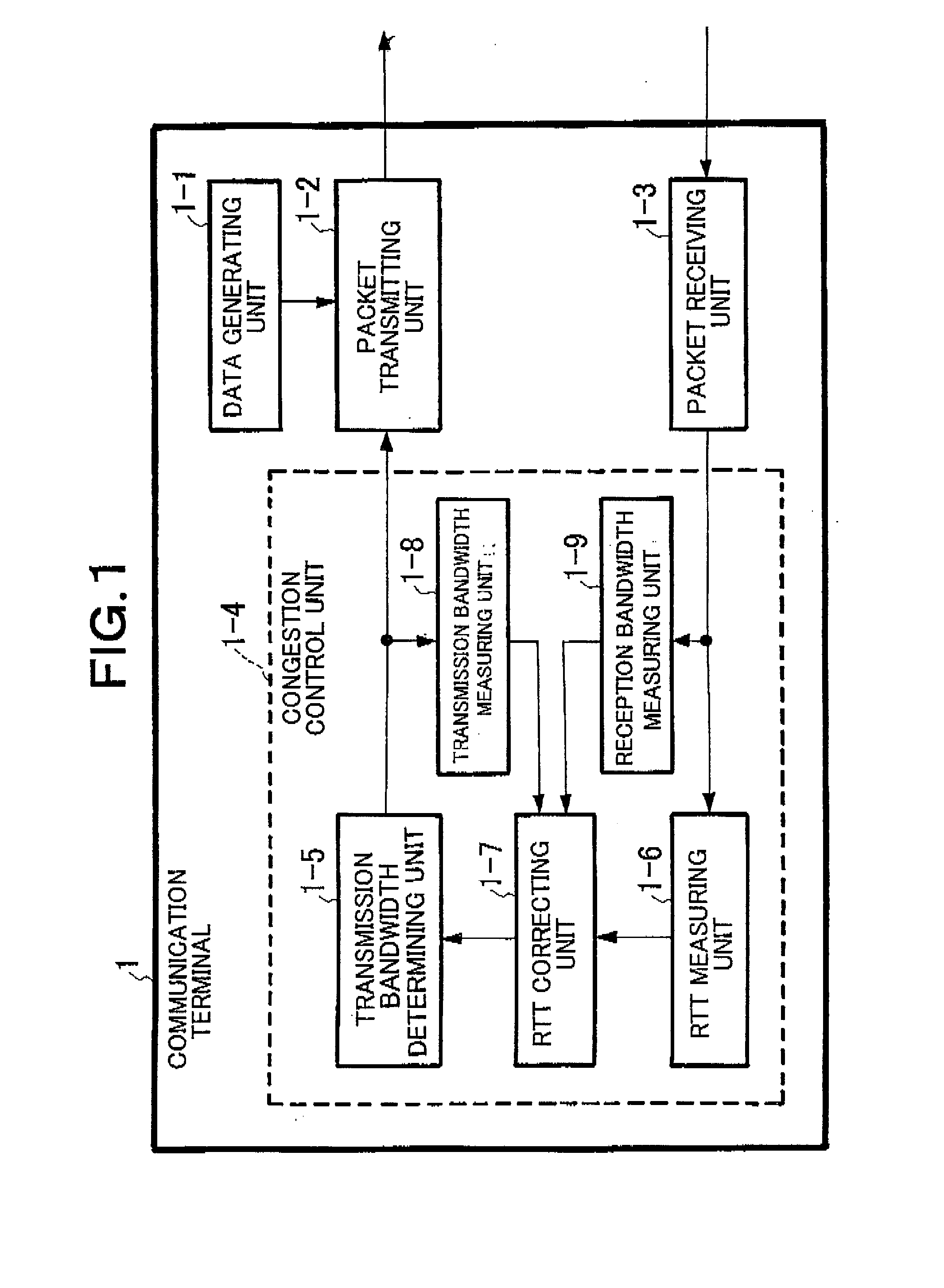
[0072]FIG. 1 is a block diagram showing a configuration of a communication terminal 1 according to the exemplary embodiment. The communication terminal 1 serving as a transmission terminal is constituted by a data generating unit 1-1 which generates transmission data, a packet transmitting unit 1-2 which outputs communication data to a network, a packet receiving unit 1-3 which receives an acknowledgement packet (ACK packet) from another communication terminal (reception terminal) which communicates with the communication terminal 1, and a congestion control unit 1-4 which designates a transmission bandwidth for the packet transmitting unit 1-2.

[0073]The congestion control unit 1-4 is constituted by an RTT (Round Trip Time) measuring unit 1-6 which measures round-trip delay time each time an ACK packet is received, a transmission bandwidt...

second exemplary embodiment

[0093]A second exemplary embodiment of the present invention will be described below with reference to the accompanying drawings.

[0094](Explanation of Configuration)

[0095]FIG. 3 is a block diagram showing a configuration of a communication terminal 2 according to the second exemplary embodiment. The second exemplary embodiment is different from the first exemplary embodiment in that an in-transmission data amount measuring unit is arranged in place of the transmission bandwidth measuring unit.

[0096]The communication terminal 2 is constituted by a data generating unit 2-1 which generates transmission data, a packet transmitting unit 2-2 which outputs communication data to a network, a packet receiving unit 2-3 which receives an acknowledgement packet (ACK packet) from a reception terminal, and a congestion control unit 2-4 which designates a transmission bandwidth for the packet transmitting unit 2-2.

[0097]The congestion control unit 2-4 is constituted by an RTT measuring unit 2-6 wh...

third exemplary embodiment

[0106]A third exemplary embodiment of the present invention will be described below with reference to the accompanying drawings.

[0107](Explanation of Configuration)

[0108]FIG. 5 is a block diagram showing a configuration of a communication terminal 3 according to the exemplary embodiment. The communication terminal 3 has a configuration by adding a transmission bandwidth increase range changing unit 3-10 to the configuration of the communication terminal 1 according to the first exemplary embodiment.

[0109]The communication terminal 3 is constituted by a data generating unit 3-1 which generates transmission data, a packet transmitting unit 3-2 which outputs communication data to a network, a packet receiving unit 3-3 which receives an acknowledgement packet (ACK packet) from another communication terminal which communicates with the communication terminal 3, and a congestion control unit 3-4 which designates a transmission bandwidth for the packet transmitting unit 3-2.

[0110]The conge...


PUM


Abstract

A communication terminal which sets a communication session between a plurality of communication terminals through a network to perform data transmission and reception includes a measuring unit which measures round-trip delay time (RTT) or one-way delay time between the communication terminals for performing transmission and reception on the basis of the received acknowledgement, a reception bandwidth measuring unit which measures a reception bandwidth in a reception terminal of the communication terminals on the basis of the received acknowledgement, a correcting unit which corrects a value of the round-trip delay time or the one-way delay time by using at least the reception bandwidth, and a transmission bandwidth determining unit which determines a transmission bandwidth on the basis of the value of the corrected round-trip delay time or the corrected one-way delay time.

Description

BACKGROUND OF THE INVENTION[0001]1. Field of the Invention[0002]The present invention relates to a communication terminal, a communication system, a congestion control method, and a congestion control program, and particular, a communication terminal, a communication system, a congestion control method, and a congestion control program which perform low-delay communication by using a broadband line.[0003]This application is based upon and claims the benefit of priority from Japanese patent application No. 2007-024525, filed on Feb. 2, 2007, the disclosure of which is incorporated herein in its entirety by reference.[0004]2. Related Art[0005]In communication through a network, in order to low-delay communication between transmission and reception terminals, delay time by a queueing delay in the network is required to be shortened. A minimum value of delay between the transmission and reception terminals is propagation delay time between the transmission and reception terminals, and c...

Claims


Application Information

Patent Timeline
Patent Type & Authority Applications(United States)
IPC IPC(8): H04L1/00H04L12/801H04L12/841H04L12/911
CPCH04L1/187H04L41/0896H04L43/0858H04L43/0864H04L47/30H04L43/0888H04L47/10H04L47/11H04L47/283H04L43/0882
Inventor SHIMONISHI, HIDEYUKI
Owner NEC CORP
Why Eureka
Try Eureka