Apparatus and method for allocating resources in a single carrier-frequency division multiple access system

a technology of multiple access system and carrier frequency division, applied in electrical equipment, digital transmission, wireless commuication services, etc., can solve the problems of difficult frequency selective scheduling, inability to ensure a relatively good channel status of the ue, and ineffective frequency selective scheduling

Active Publication Date: 2008-09-04
UNWIRED PLANET INT LTD
View PDF9 Cites 35 Cited by
  • Summary
  • Abstract
  • Description
  • Claims
  • Application Information

AI Technical Summary

Benefits of technology

[0019]An aspect of the present invention is to address at least the problems and / or disadvantages and to provide at least the advantages described below. Accordingly, an aspect of the present invention is to provide a method and apparatus for allocating resources to randomize interference between neighbor cells when mirroring is adopted to achieve frequency diversity.

Problems solved by technology

However, the frequency selective scheduling is not always effective.
For a UE that moves fast and thus experiences a fast change in channel status, the frequency selective scheduling is not easy.
Hence, the selected frequency band does not ensure a relatively good channel status for the UE.
Even in a Voice over Internet Protocol (VoIP)-like service that requires a small amount of frequency resources continuously for data transmission, if the UE reports its channel status for the frequency selective scheduling, signaling overhead can be substantial.
The frequency hopping has the effect of randomizing channel quality and interference during data transmission.
However, the frequency hopping is not viable when RUs hop in independent patterns in the SC-FDMA system as illustrated in FIG. 3.
This means that frequency diversity is achieved to a certain degree but interference randomization is difficult.
If the UE of Cell B is near Cell A, it causes substantial interference to UEs in Cell A. As a result, the UE of Cell A using RUs marked with dots suffers from reception quality degradation.

Method used


Image

  • Apparatus and method for allocating resources in a single carrier-frequency division multiple access system
  • Apparatus and method for allocating resources in a single carrier-frequency division multiple access system
  • Apparatus and method for allocating resources in a single carrier-frequency division multiple access system

Examples


embodiment 1

[0050]Embodiment 1 provides a method for turning mirroring on or off according to a different mirroring on / off pattern for each cell. Using different mirroring on / off patterns for different cells as much as possible and decreasing the probability of mirroring-on in cells at the same time maximize the effect of randomizing interference between cells.

[0051]FIGS. 5A and 5B illustrate a method according to the first embodiment of the present invention. FIG. 5A illustrates slot-based mirroring irrespective of HARQ and FIG. 5B illustrates independent mirroring for each HARQ process.

[0052]Referring to FIG. 5A, there are cells 501 and 502 (Cell A and Cell B). As intra-subframe hopping is assumed, the hopping period is a slot. On a slot basis, mirroring is performed at each hopping time in a pattern 503 of on, on, on, off, on, off, off, off . . . in Cell A, and in a pattern 512 of on, off, on, on, off, off, on, on, . . . in Cell B.

[0053]In Cell A, an RU 504 is allocated to UE A at a hopping ...

embodiment 2

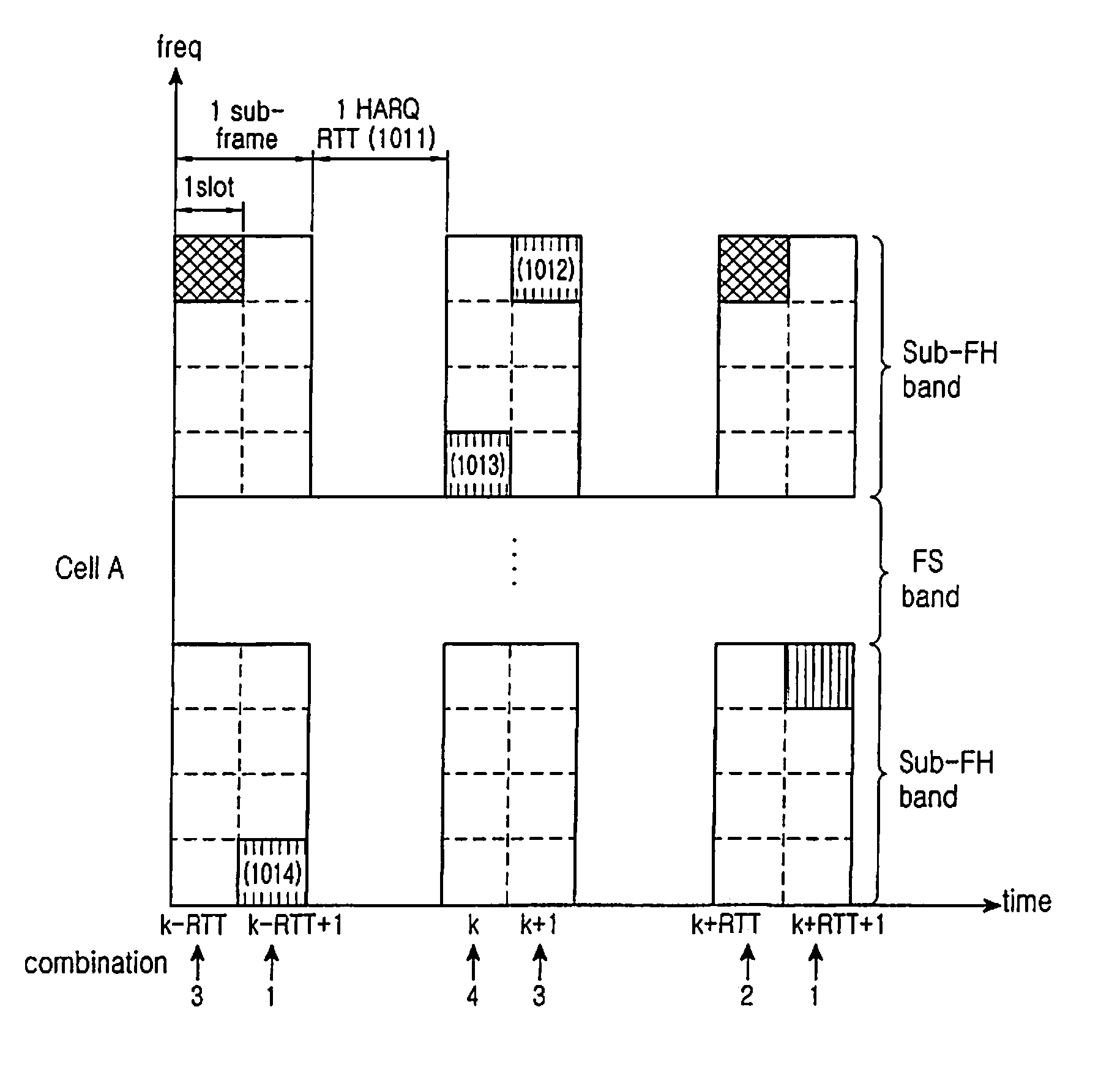
[0068]Inter-sub-FH band hopping on / off is combined with mirroring on / off and the position of an RU for data transmission is determined by selecting one of the combinations such that each cell has a different pattern. That is, the resources of a total system frequency band are divided into an FH band and an FS band, and a channel structure which offers a sufficient frequency hopping gain in the FH band and achieves a sufficiently available frequency band in the FS band is disclosed.

[0069]FIG. 9 illustrates the channel structure according to the second embodiment of the present invention.

[0070]Referring to FIG. 9, sub-FH bands 901 and 903 are defined at either side of a total frequency band and the center frequency band between the sub-FH bands 901 and 903 is defined as an FS band 902. UEs using the FS band 902 can hop to the sub-FH bands 901 and 903, thereby achieving a sufficient frequency hopping gain. As the frequencies of the FS band 902 are successive to maximize successive freq...

embodiment 3

[0087]FIG. 12 illustrates a channel structure according to a third embodiment of the present invention.

[0088]For a system where a plurality of sub-FH bands exist as illustrated in FIG. 12 and hopping always occurs between the sub-FH bands, a method is disclosed for determining mirroring on / off according to a different pattern for each cell. The use of different mirroring on / off patterns for different cells decreases the probability of performing mirroring at the same time in the different cells, thus resulting in maximized randomization of inter-cell interference.

[0089]FIGS. 13 and 14 illustrate a method according to the third embodiment of the present invention. Specifically, FIG. 13 illustrates a mirroring method independent of HARQ and FIG. 14 illustrates a method for performing mirroring on an HARQ process basis.

[0090]Referring to FIG. 13, since it is assumed that both cells 1301 and 1311 (Cell A and Cell B) support intra-subframe hopping, the hopping period is a slot. Mirroring...


PUM


Abstract

An apparatus and method for allocating resources in an Single Carrier-Frequency Division Multiple Access (SC-FDMA) communication system are provided, in which a Node B determines on a cell basis whether to turn or off inter-subband hopping and whether to turn on or off mirroring for a resource unit for the UE on a frequency axis along which at least two subbands are defined, at set hopping times, selects a resource unit by selectively performing inter-subband hopping and mirroring on the resource unit for the UE according to the determination, and allocates the selected resource unit to the UE.

Description

PRIORITY[0001]This application claims priority under 35 U.S.C. § 119(a) to Korean Patent Applications filed in the Korean Intellectual Property Office on Jan. 9, 2007 and assigned Serial No. 2007-2657, on Jun. 14, 2007 and assigned Serial No. 2007-58331, on Aug. 9, 2007 and assigned Serial No. 2007-80204, and on Dec. 7, 2007 and assigned Serial No. 2007-126476, respectively, the contents of each of which are incorporated herein by reference.BACKGROUND OF THE INVENTION[0002]1. Field of the Invention[0003]The present invention relates to a method and apparatus for efficiently allocating control channel transmission resources when a packet data channel and a control channel are transmitted in the same transmission period in a Single Carrier-Frequency Division Multiple Access (SC-FDMA) wireless communication system.[0004]2. Description of the Related Art[0005]FIG. 1 illustrates a transmitter in a Localized FDMA (LFDMA) system, which is a type of SC-FDMA system. While the transmitter is ...

Claims


Application Information

Patent Timeline
Patent Type & Authority Applications(United States)
IPC IPC(8): H04Q7/00H04B1/713H04J13/18
CPCH04B1/7143H04B2001/7154H04W72/0453H04L5/023H04J13/18H04W72/20H04W72/21H04B1/713H04W88/02H04W88/08H04W72/0446H04W72/0466
Inventor HEO, YOUN-HYOUNGLEE, JU-HORO, SANG-MINCHO, JOON-YOUNGCHO, YUN-OK
Owner UNWIRED PLANET INT LTD
Why Eureka
Try Eureka