Method of calculating internal resistance of secondary battery for vehicle

Active Publication Date: 2008-09-04
NIPPON SOKEN +1
View PDF3 Cites 23 Cited by
  • Summary
  • Abstract
  • Description
  • Claims
  • Application Information

AI Technical Summary

Benefits of technology

[0018]Because the magnitude of the maximum discharge current generated in the secondary battery at the start of the vehicle engine is adequately known, although s

Problems solved by technology

However, because the I-V characteristic of a secondary battery such as a lead storage battery is much changed and a polarization state of the secondary battery is thereby largely varied, it is difficult to obtain the internal resistance based on the I-V characteristic of the secondary battery for a motor vehicle with high accuracy.
The internal resistance calculation method further requires a current sensor capable of measuring a large currant within a wide current range with desired high accuracy in order to measure a starting current when a vehicle engine starts within a full detection range such as from −1000 A to −600 A. The current sensor having such a capability is extremely expensive because it guarantees a desired accuracy at any detect

Method used


Image

  • Method of calculating internal resistance of secondary battery for vehicle
  • Method of calculating internal resistance of secondary battery for vehicle
  • Method of calculating internal resistance of secondary battery for vehicle

Examples


Example

First Embodiment

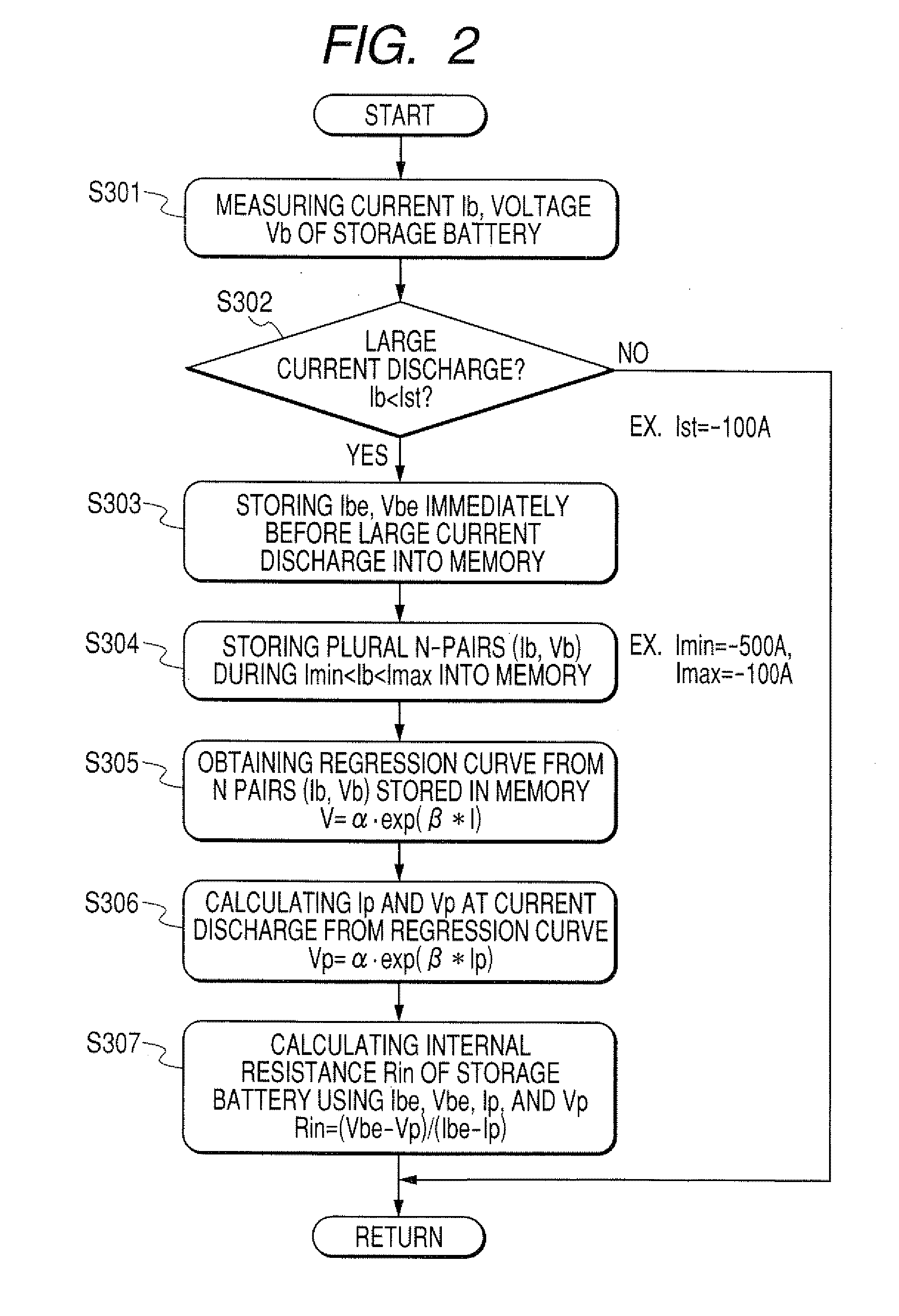
[0033]A description will be given of an internal state detection device capable of performing a method of calculating an internal resistance of a secondary battery (or a storage battery) mounted on a motor vehicle according to the present invention. The method according to the first embodiment performs a curve approximation using an exponential curve (as a regression characteristic line) for a current-voltage characteristic of the secondary battery.

(Circuit Configuration)

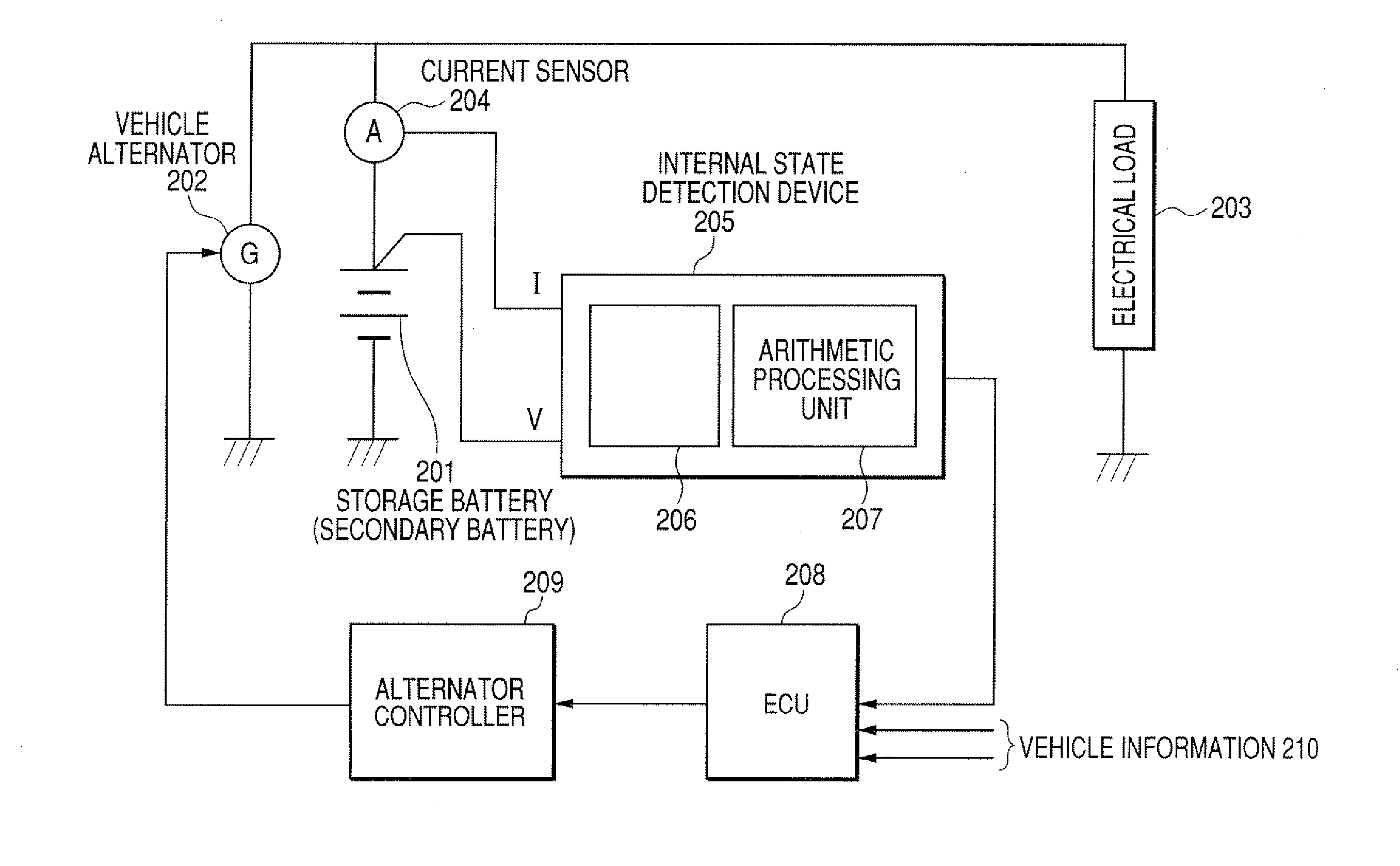
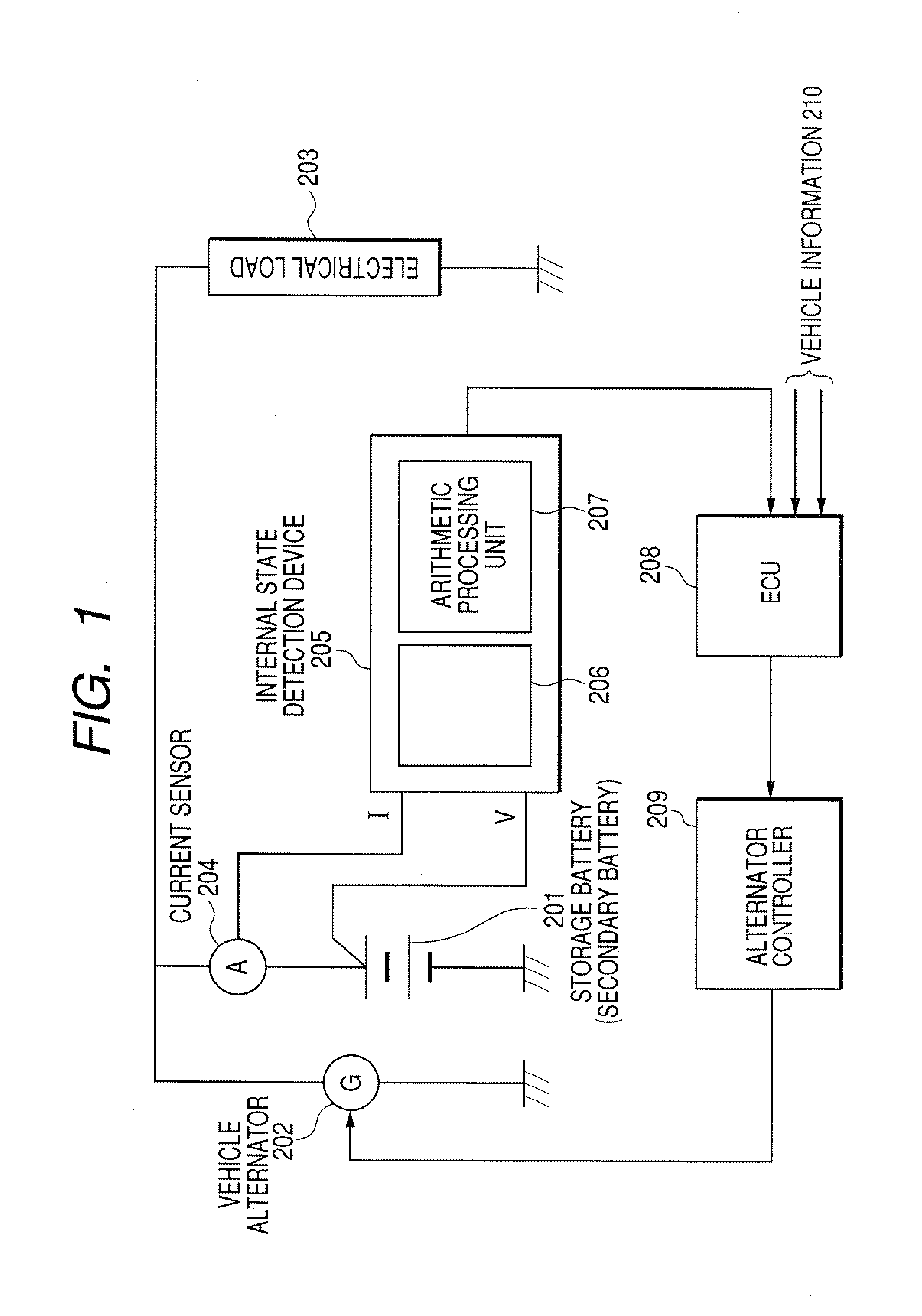
[0034]The internal resistance detection device according to the first embodiment capable of detecting an internal state of a storage battery (or a secondary battery) will be explained with reference to FIG. 1.

[0035]FIG. 1 is a block diagram mainly showing a circuit configuration of the internal state detection device according to the first embodiment of the present invention. In FIG. 1, reference number 201 designates a storage battery (or a secondary battery) mounted on a motor vehicle, which is a d...

Example

Second Embodiment

[0065]A description will be given of the method of calculating the internal resistance of the storage battery based on a linear approximation using a straight line (as the regression characteristic line) for the current-voltage characteristic of the secondary battery 201 instead of the method of the first embodiment which performs the curve approximation using an exponential curve (as the regression characteristic line) for the current-voltage characteristic of the secondary battery 201.

[0066]FIG. 8 is a flow chart showing the method of calculating the internal resistance of the storage battery according to the second embodiment of the present invention. The internal resistance calculation procedure of the method according to the second embodiment will be explained with reference to the flow chart shown in FIG. 8.

[0067]First, the current Ib and the voltage Vb of the storage battery are measured (Step S801). That is, the internal state detection device 205 measures t...


PUM


Abstract

A current Ibe and a voltage Vbe before a large current discharge in a secondary battery are stored in a memory. Plural voltage-current pairs are detected and stored in the memory during the large current discharge. Next, a regression curve (or a regression line) is obtained based on the plural voltage-current pairs stored in the memory using a well-known method. A discharge current Ip which exceeds a current-sensor detectable range is input in the regression curve to obtain a voltage Vp. A maximum discharge coordinate is set using the discharge current Ip and the voltage Vp. An internal resistance Rin of the secondary battery is calculated based on an inclination of a line that connects the coordinates (Ibe, Vbe) and (Ip, Vp).

Description

CROSS-REFERENCE TO RELATED APPLICATION[0001]This application is related to and claims priority from Japanese Patent Application No. 2007-53227 filed on Mar. 2, 2007, the contents of which are hereby incorporated by reference.BACKGROUND OF THE INVENTION[0002]1. Field of the Invention[0003]The present invention relates to an improved method of calculating an internal resistance of a secondary battery (or a storage battery) mounted on a motor vehicle.[0004]2. Description of the Related Art[0005]An internal resistance as one of internal impedances of a secondary battery (or a storage battery) mounted on a motor vehicle is a well-known important parameter in order to judge a deterioration state of and a charge state of the secondary battery, For example, using an internal resistance as an input parameter into a Neural network simulator capable of performing a state of charge (SOC) calculation can detect a SOC of the secondary battery with high accuracy.[0006]Related art techniques calcul...

Claims


Application Information

Patent Timeline
IPC IPC(8): H01M10/48G06F19/00B60R16/04G01R31/36H02J7/00
CPCG01R31/006G01R31/3662G01R31/3693H01M10/48G01R31/3624H01M10/4257G01R31/3647G01R31/3842G01R31/389Y02E60/10
Inventor MIZUNO, SATORUSAKAI, SHOJIONO, HIROAKI
Owner NIPPON SOKEN
Why Eureka
Try Eureka