Tracheostomy Tube

a tracheostomy tube and trachea technology, applied in the field of medical devices and surgical devices, can solve the problems of tracheal tubes affecting the other important upper airway tracheal tubes can interfere with the other important functions of the trachea, and tracheal tubes can also be destructive to the surrounding tissues and organs, so as to reduce the risk of damage to the mucosa, prevent distal occlusion, and the risk of occlusion

Inactive Publication Date: 2008-09-11
PEDIATRIC AIRWAY INNOVATIONS LLC
View PDF11 Cites 36 Cited by
  • Summary
  • Abstract
  • Description
  • Claims
  • Application Information

AI Technical Summary

Benefits of technology

[0011]The present invention provides an improved tracheostomy tube with a rigid proximal section, a flexible mid-section, and a rigid distal section. In a preferred embodiment, the tip of the tube does not tend to rub the anterior or the posterior wall of the trachea. The flexible middle section typically has a smooth surface and bends within the trachea and allows the distal rigid section of the tracheotomy tube to lie reasonably parallel with the lumen of the section of the trachea within which it resides. The tube of the invention a so includes a modified tip design with a beveled end to provide a greater cross-sectional area at the tube's distal end and to prevent distal occlusion of the tube by the tracheal walls. The tube can also include a beaded or rounded edge within the tip of the distal shaft to minimize the risk of damage to the mucosa and also to provide a guide to the clinical care specialist when suctioning the distal section of the tube.

Problems solved by technology

The human body is far too complicated to be easily replaced by artificial parts, and the upper airway is no exception.
While helpful to secure airways and save lives, tracheal tubes can interfere with the other important upper airway functions of the trachea.
If they are needed for an extended period of time, tracheal tubes can also be destructive to the surrounding tissues and organs.
The disadvantage of a pre-curved tube is that the curve may not suit an individual's particular anatomy, and therefore the tip of the tube may impinge upon the anterior or posterior wall of the trachea.
The disadvantage of a flexible tube is that the default shape of the tube is straight, and although it will conform to the curve of the tracheostomy tract, it will have a tendency to impinge the posterior wall of the trachea.
One fundamental dilemma common to all tracheal tube designs is that they must have at least some rigidity in order not to kink or collapse, otherwise they are not effective conduits for air, yet they must be gentle on the airway structures.
Unfortunately, the rigidity of the tubes invariably causes some force to be applied to the mucosa of the trachea.
Even despite devoted clinical care, tracheal tubes routinely result in ischemic areas of the tracheal mucosa.
Indeed, the complications associated with prolonged intubation can be particularly severe.
Persistent irritation of the cartilaginous support of the trachea causes destruction of structures.
Later, scarring and stricture formation will result within the trachea once the irritation is removed.
Ischemia routinely results in pressure necrosis, ulceration, granulation formation and scarring of the tracheal mucosa.
Long term use of a tracheostomy tube often leads to suprastomal granulation tissue formation, suprastomal collapse, and tracheal wall erosion due to the tip of the tube impinging on the interior tracheal wall.
This problem arises because the open distal ends of currently used tracheostomy tubes have tips that are cut flush at a 90° angle to the shaft.
A secondary problem that arises at the distal end of the tube is that deep suctioning of secretions through the tube may cause damage (granulation or stenosis) to the trachea and bronchi.
This occurs because the suction catheter used to perform this maneuver is typically unknowingly extended past the tip of the tube and makes contact with the tracheal and bronchial surfaces, thereby causing the damage.

Method used


Image

  • Tracheostomy Tube
  • Tracheostomy Tube
  • Tracheostomy Tube

Examples


Embodiment Construction

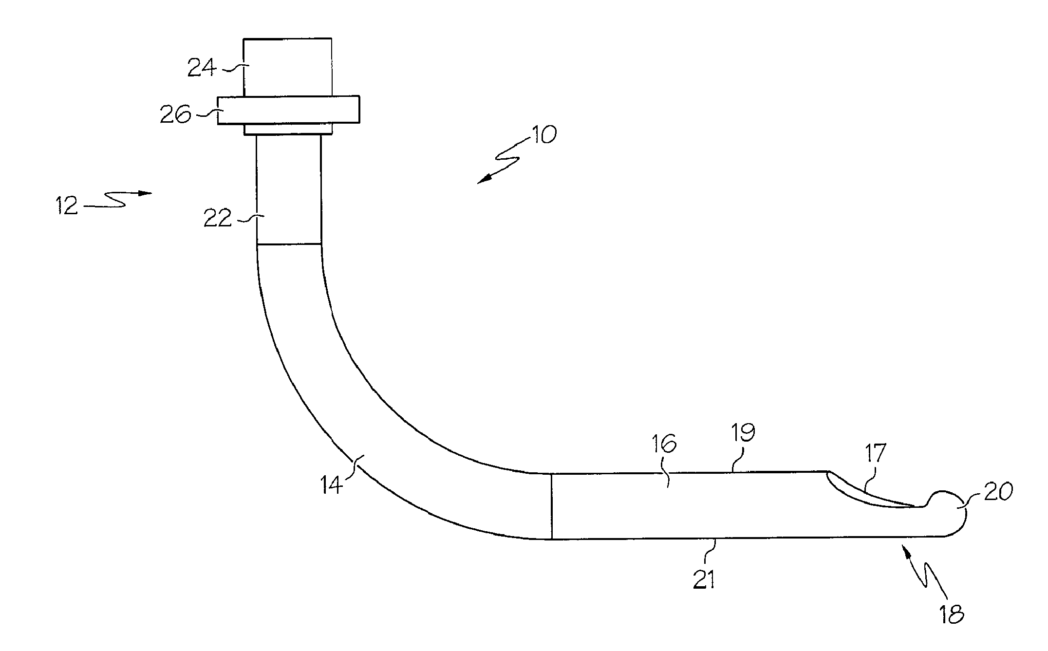
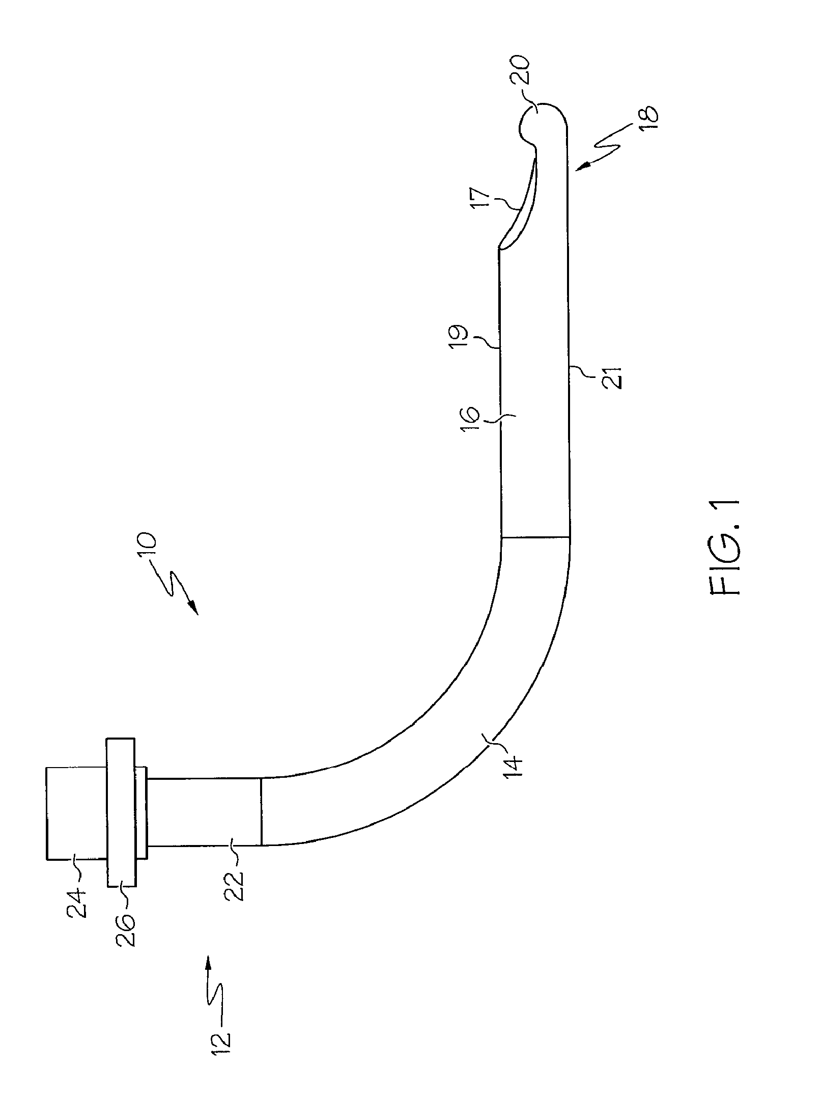
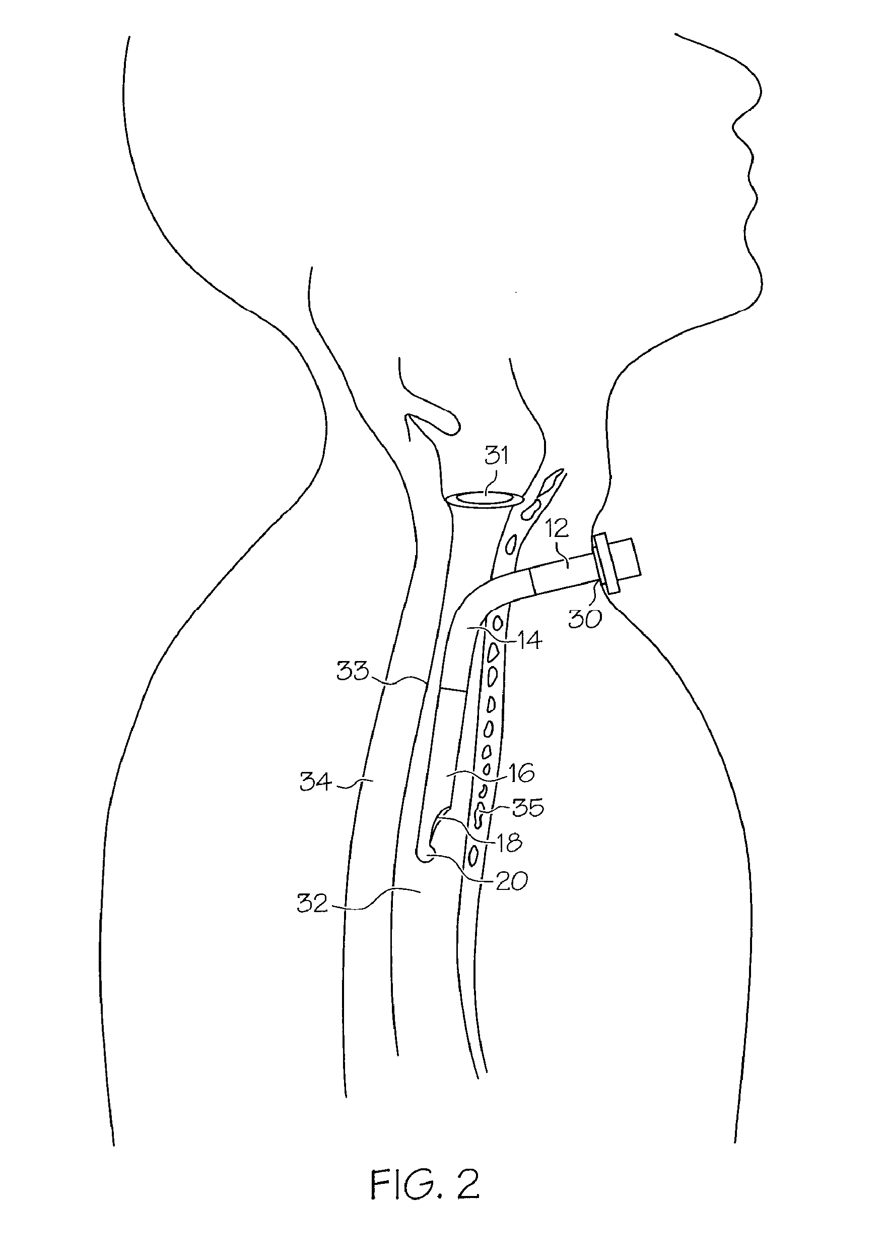
[0019]The tracheostomy tube of the invention is intended for use in children and adults with tracheomalacia, as well as in children and adults in whom the tip of the tracheotomy tube is prone to become either partly obstructed within the trachea, or is at risk of causing mucosal damage. The intermediate section of the tube is flexible, which allows the distal section of the tube to safely move within the trachea as the trachea moves. The tip of the tube, at its distal section, typically includes a beveled end with a large cross-sectional area, whereby the posterior aspect of the distal shaft is longer than the anterior aspect of the distal shaft. The tube thus does not have a tendency to become obstructed at its distal end, or cause erosion of the tracheal mucosa, as do prior art tubes.

[0020]FIG. 1 is a plan view according to a first embodiment of the present invention. In particular, FIG. 1 shows a tracheostomy tube 10 having a proximal or machine end section 12. A flexible interme...


PUM


Abstract

An improved tracheostomy tube providing a decreased tendency to produce rubbing, pressure necrosis, ulceration and scarring of the tracheal mucosa. The tube typically includes a rigid proximal section, a flexible intermediate section, a rigid distal section, and a beveled distal tip. The flexible intermediate section has a smooth surface and bends easily in response to pressure asserted by the tracheal walls, allowing the distal rigid section of the tube to remain in a parallel orientation relative to the tracheal lumen, The distal tip of the tube is beveled to provide a greater cross-sectional area at the tube's distal section. This beveled distal tip prevents the distal section of the tube from becoming obstructed by the back wall of the trachea or causing erosion of the tracheal mucosa. The distal tip also has a beaded or rounded edge, which further minimizes the risk of damage to the tracheal mucosa and provides a guide to the clinical care specialist during suctioning.

Description

FIELD OF THE INVENTION[0001]The invention relates generally to medical and surgical devices and in particular to a tracheostomy tube with a flexible mid-shaft design.BACKGROUND OF THE INVENTION[0002]The human body is far too complicated to be easily replaced by artificial parts, and the upper airway is no exception. The upper airway performs a multitude of functions, the simplest being that of a conduit from the atmosphere to the lungs. Other important functions of the upper airway include humidification and filtration of air, mounting of an immune response to outside infectious agents, removal of debris by deglutition (swallowing) and expectoration (spitting), and speech.[0003]Tracheal tubes are artificial conduits which are commonly inserted into an individual's trachea to enable them to breathe, or to deliver anesthetic gases to an unconscious patient. Tracheal tubes are often required to artificially ventilate an individual in critical clinical situations. While helpful to secur...

Claims


Application Information

Patent Timeline
Patent Type & Authority Applications(United States)
IPC IPC(8): A61M16/00A61F2/20
CPCA61M16/0465A61M16/0418A61M2205/0222
Inventor RUTTER, MICHAEL JOHN
Owner PEDIATRIC AIRWAY INNOVATIONS LLC
Why Eureka
Try Eureka