Substrate treatment apparatus

Active Publication Date: 2008-09-11
DAINIPPON SCREEN MTG CO LTD
View PDF15 Cites 16 Cited by
  • Summary
  • Abstract
  • Description
  • Claims
  • Application Information

AI Technical Summary

Benefits of technology

[0018]An object of the present invention is to provide a substrat

Problems solved by technology

Major problems in the substrate treatment apparatus of the prior art described above are, first, a low substrate treatment speed (throughput), and second, the expense.
In addition, the multijoint arm type robot itself is expensive.
Further, a space for swiveling the multijoint arm is necessary, so that the area occupied substantially by the apparatus is large.
The operation time of this substrate alignment mechanism strains the substrate treatment speed.
In addition to the substrate alignment mechanism, the posture changing mechanism must be provided with a horizontal substrate guide for holding substrates in the horizontal postures, a vertical substrate guide for holding substrates in the vertical postures, and a pivotal mechanism for changing the postures of the substrates, which is an extremely expensive robot.
Further, the pusher includes a vertical movement mechanism, a horizontal movement mechanism, and a rotation mechanism, and is also expensive.
Thus, the time required to convey the substrates between the carrier (container) and the conveyance mechanism contributes to hamper improvement in throughput.
The construction for substrate conveyance between the carrier (container)

Method used


Image

  • Substrate treatment apparatus
  • Substrate treatment apparatus
  • Substrate treatment apparatus

Examples


first embodiment

Entire Construction of First Embodiment

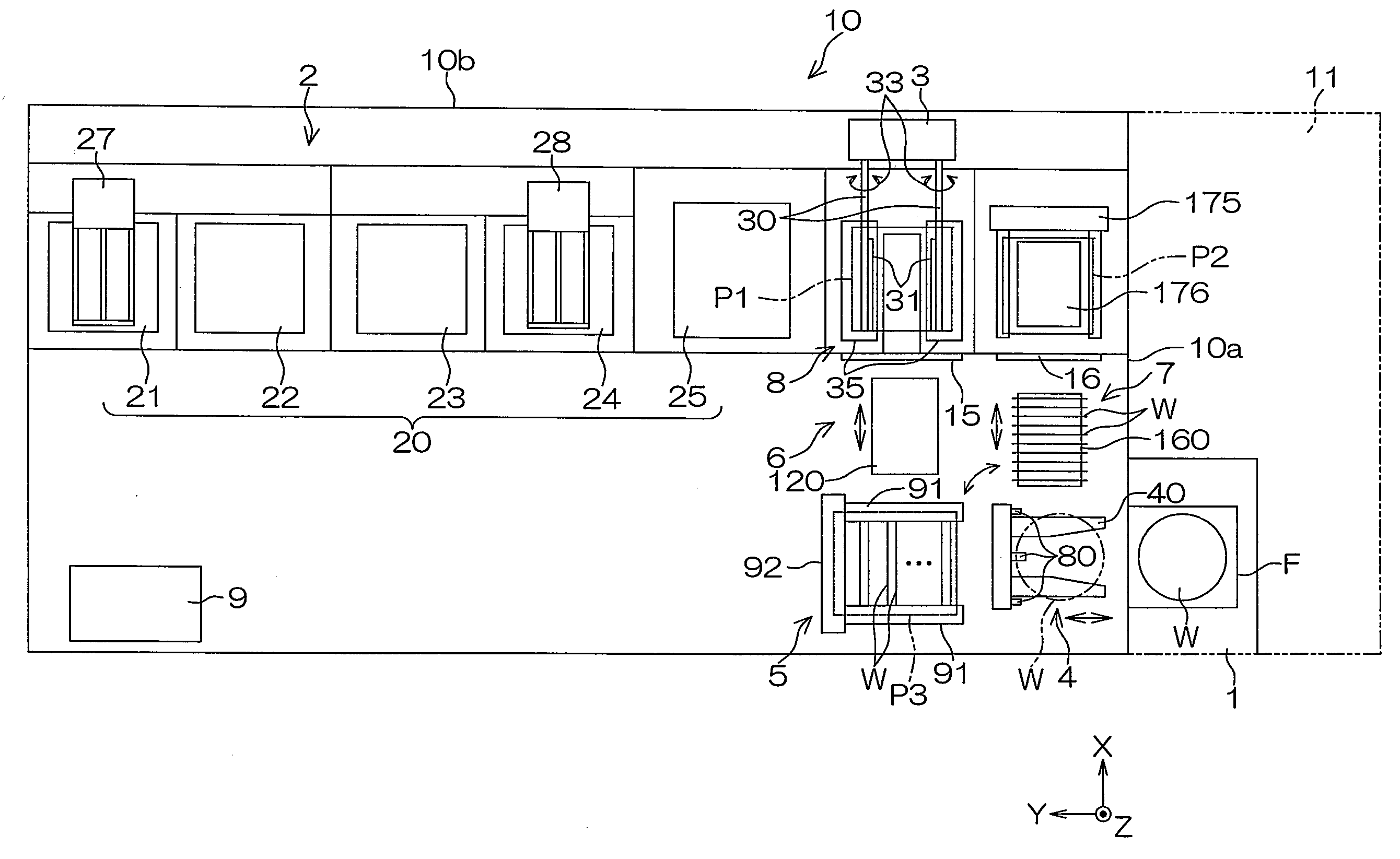
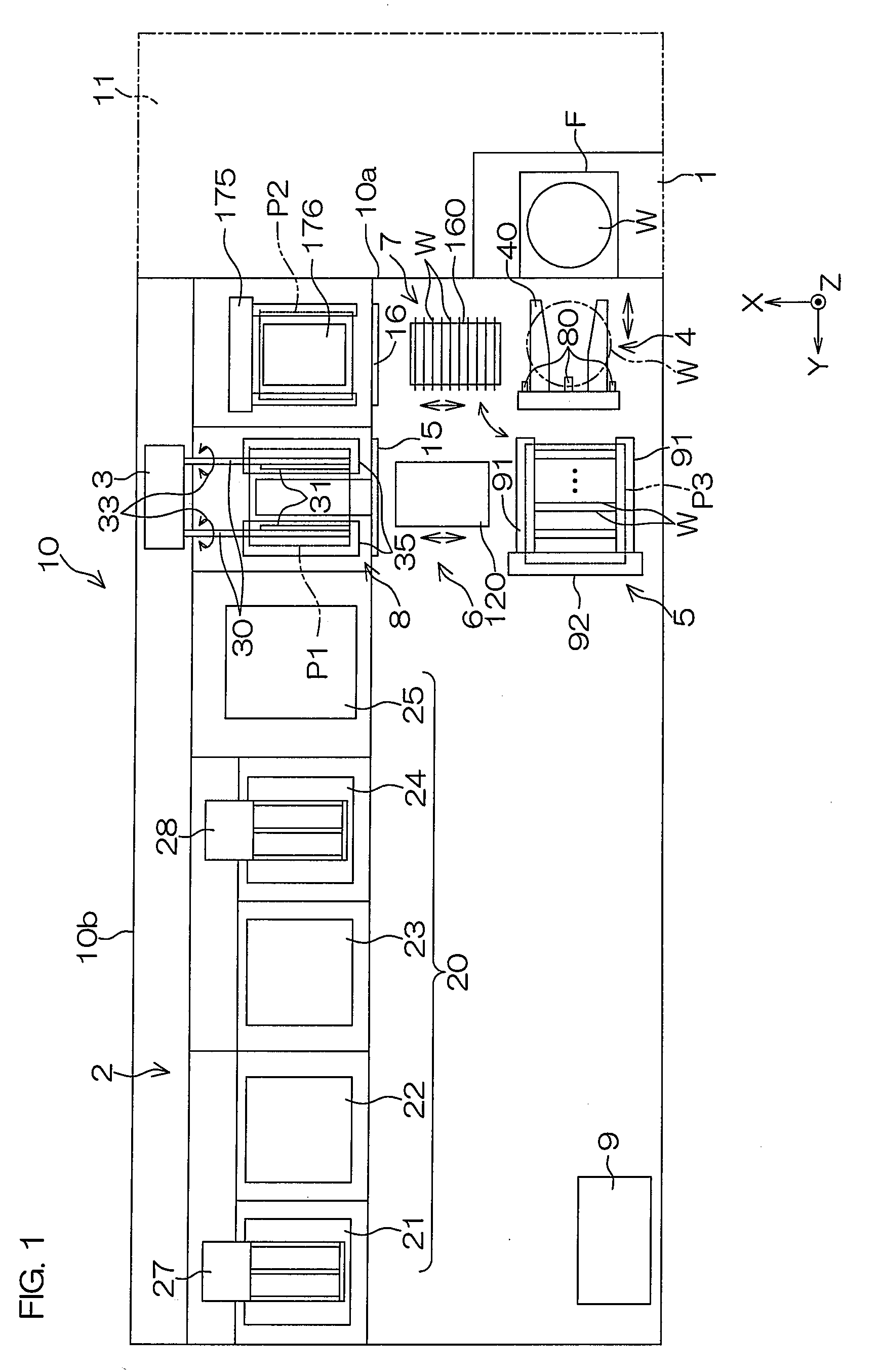
[0100]FIG. 1 is a schematic plan view for describing an entire construction of a substrate treatment apparatus of an embodiment of the present invention. This substrate treatment apparatus 10 includes a FOUP holder 1, a substrate treatment section 2, a main conveyance mechanism 3, a carrying in / out mechanism 4, a transfer mechanism 5, a first horizontal conveyance mechanism 6, a second horizontal conveyance mechanism 7, a chuck cleaning unit 8, and a controller 9 (control unit).

[0101]The FOUP holder 1 is disposed at one corner of the substrate treatment apparatus 10 shaped into substantially a rectangle in a plan view. This FOUP holder 1 is a container holder which can hold a FOUP F as a container for containing multiple substrates W in the horizontal postures stacked in a Z direction (vertical direction, perpendicular direction). An automatic FOUP conveyance device 11 shown by the alternate long and two short dashed line is disposed so as to f...

second embodiment

[0200]FIG. 25 is a plan view showing a construction of a substrate treatment apparatus according to another embodiment of the present invention. FIG. 26 is a schematic perspective view showing a construction between a FOUP and a substrate delivery position.

[0201]In the first embodiment described above, the main conveyance mechanism 3 delivers treated substrates W to the first horizontal conveyance mechanism 6 at the first substrate delivery position P1, and receives untreated substrates W conveyed by the second horizontal conveyance mechanism 7 at the second substrate delivery position P2. On the other hand, in the substrate treatment apparatus 200 of the present embodiment, the second horizontal conveyance mechanism 7 is omitted, and only one horizontal conveyance mechanism 6 is provided. This horizontal conveyance mechanism 6 delivers untreated substrates W to the main conveyance mechanism 3 at the substrate delivery position P1, and receives treated substrates W from the main con...


PUM


Abstract

A substrate treatment apparatus includes a container holder which holds a container for containing multiple substrates vertically stacked in horizontal postures, a substrate treatment section which collectively applies treatment to multiple substrates horizontally stacked in vertical postures, a main conveyance mechanism which conveys multiple substrates horizontally stacked in vertical postures between a substrate delivery position and the substrate treatment section, a carrying in/out mechanism which carries in/out the multiple substrates with respect to the container and changes postures of the multiple substrates between the horizontal postures and the vertical postures, and a sub conveyance mechanism which receives and delivers multiple substrates in vertical postures from and to the carrying in/out mechanism at a transfer position, receives and delivers multiple substrates in vertical postures from and to the main conveyance mechanism at the substrate delivery position, and conveys multiple substrates in vertical postures between the transfer and substrate delivery positions.

Description

BACKGROUND OF THE INVENTION[0001]1. Field of the Invention[0002]The present invention relates to a substrate treatment apparatus which applies treatment to multiple substrates collectively. Substrates to be subjected to treatment include, for example, semiconductor wafers, liquid crystal display device substrates, plasma display substrates, FED (Field Emission Display) substrates, optical disk substrates, magnetic disk substrates, magneto-optical disk substrates, and photo mask substrates.[0003]2. Description of Related Art[0004]A substrate treatment apparatus which applies treatment using a chemical to substrates such as semiconductor wafers includes a batch type which applies treatment to multiple substrates collectively. An example of the batch type substrate treatment apparatus is shown in Japanese Unexamined Patent Publication No. H11-354604. This substrate treatment apparatus includes a carrier mounting section, a horizontal transfer robot, a posture changing mechanism, a push...

Claims


Application Information

Patent Timeline
IPC IPC(8): B08B13/00
CPCH01L21/67075H01L21/67781H01L21/67766Y10S134/902
Inventor SHIOMI, AKIONISHINA, YOSHIHIROSATO, TORUMURAMOTO, RYO
Owner DAINIPPON SCREEN MTG CO LTD
Why Eureka
Try Eureka