
Power Supply Device

a power supply device and power supply technology, applied in power supply testing, instruments, transportation and packaging, etc., can solve the problems of inability to detect abnormalities, and inability to guarantee operation, so as to achieve high reliability. the effect of ensuring

Inactive Publication Date: 2008-09-11
PANASONIC CORP
View PDF3 Cites 13 Cited by
  • Summary
  • Abstract
  • Description
  • Claims
  • Application Information

AI Technical Summary

Benefits of technology

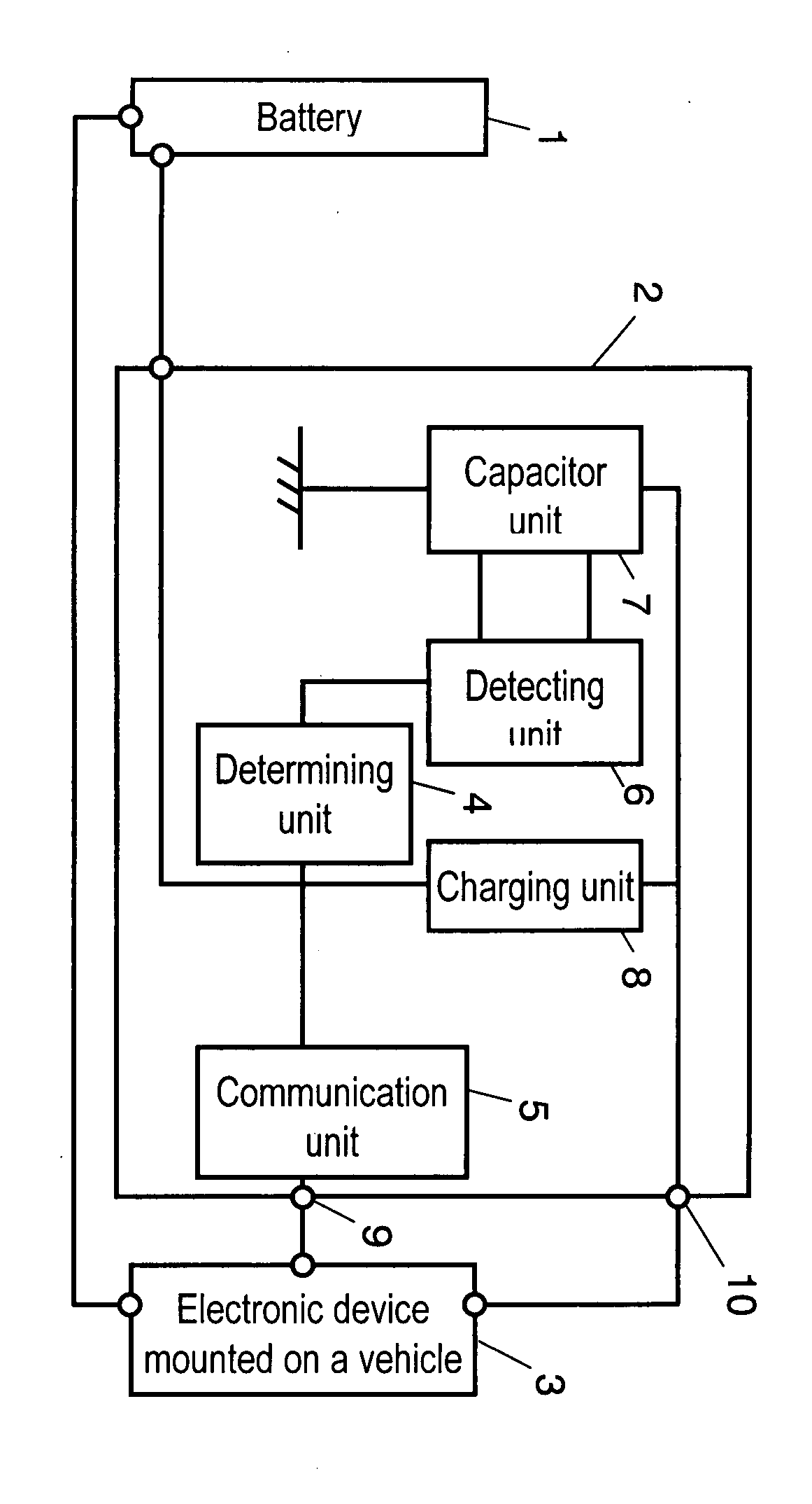
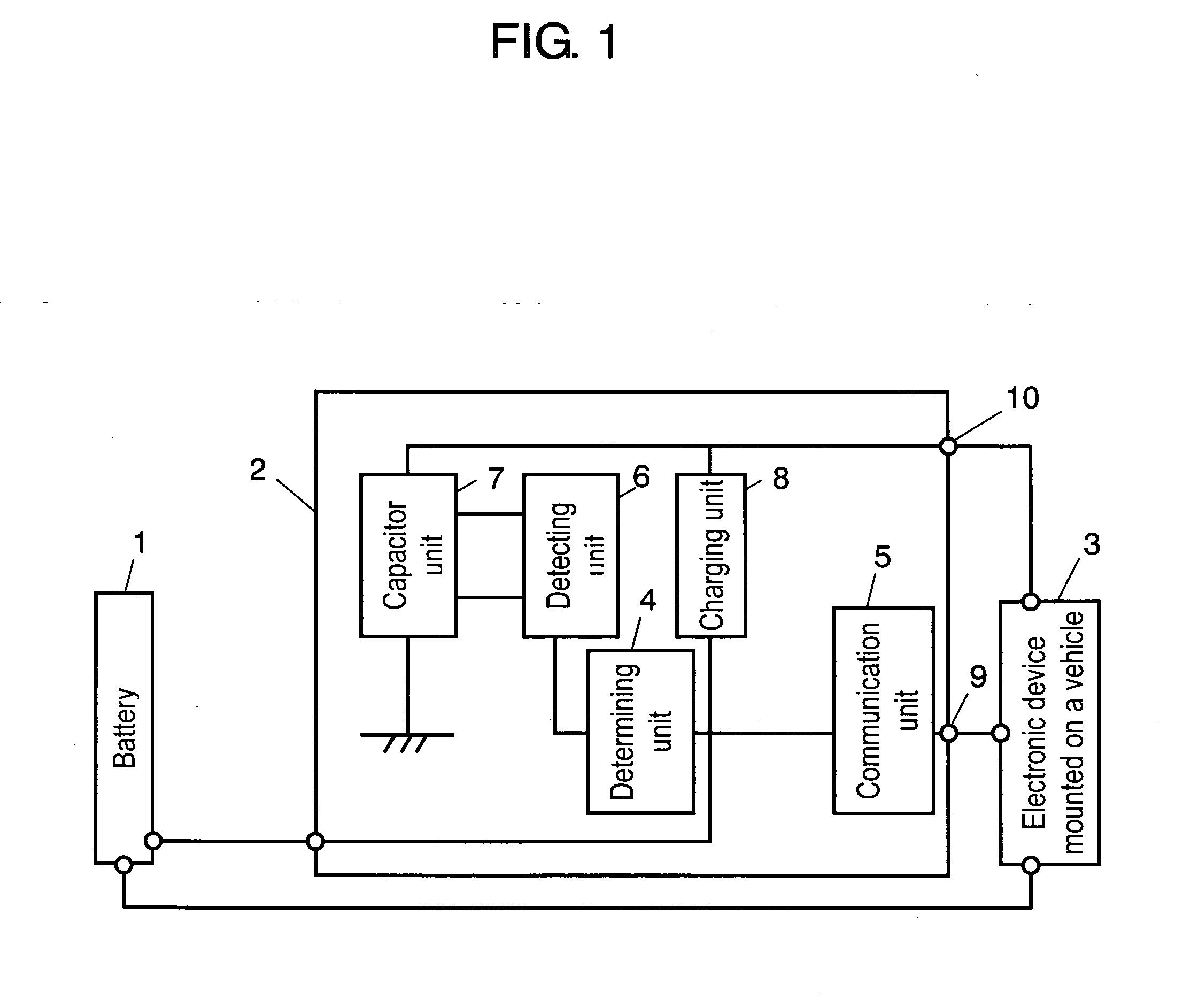
[0005]A power supply device of the present invention has the following elements: a capacitor unit in which capacitors are interconnected in series or in series-parallel; a charging unit for charging the capacitor unit at a constant current; a detecting unit for detecting voltage on the high potential side of each of the capacitors; a determining unit for determining the existence of an abnormality based on the voltage detected by the detecting unit; and a communication unit for outputting a determining result from the determining unit. The determining unit determines the abnormality when difference between respective voltages on the high potential sides of some adjacent capacitors exceeds upper-limit voltage value Va, when the difference is lower than lower-limit voltage value Vb, or when one of respective voltages is negative. Thus, by detecting an abnormal voltage applied to each capacitor or a short failure, the abnormality detection of the capacitor unit is enabled, and hence the high reliability can be guaranteed.

Problems solved by technology

The severest application is usage as a power supply for a backup operation when the main power supply fails.
However, even when an abnormality occurs in a single capacitor, it is disadvantageously difficult to detect the abnormality as a large variation in the whole capacitor unit.
When a balance operation circuit fails, the abnormality cannot be detected.
When a backup operation by the capacitor unit is required in an emergency state, the operation is not guaranteed.

Method used


Image

  • Power Supply Device
  • Power Supply Device
  • Power Supply Device

Examples


Embodiment Construction

[0010]An exemplary embodiment of the present invention will be hereinafter described with reference to the drawings. FIG. 1 is a block diagram of a power supply device having capacitors for storage as an emergency backup power supply device for an electronic device mounted on a vehicle.

[0011]For extending the life of capacitor unit 7 formed of electrical double layer capacitors, capacitor unit 7 is needed to be kept in no charge state while being not used. The capacitor unit is discharged when a user gets off a vehicle, and is charged from a battery when the user gets on the vehicle. When the capacitor unit is recharged as necessary in use, it is charged at a constant current by charging unit 8. When battery 1 comes off to turn off power, namely in an emergency, capacitor unit 7 applies energy to electronic device 3 mounted on the vehicle through backup output terminal 10.

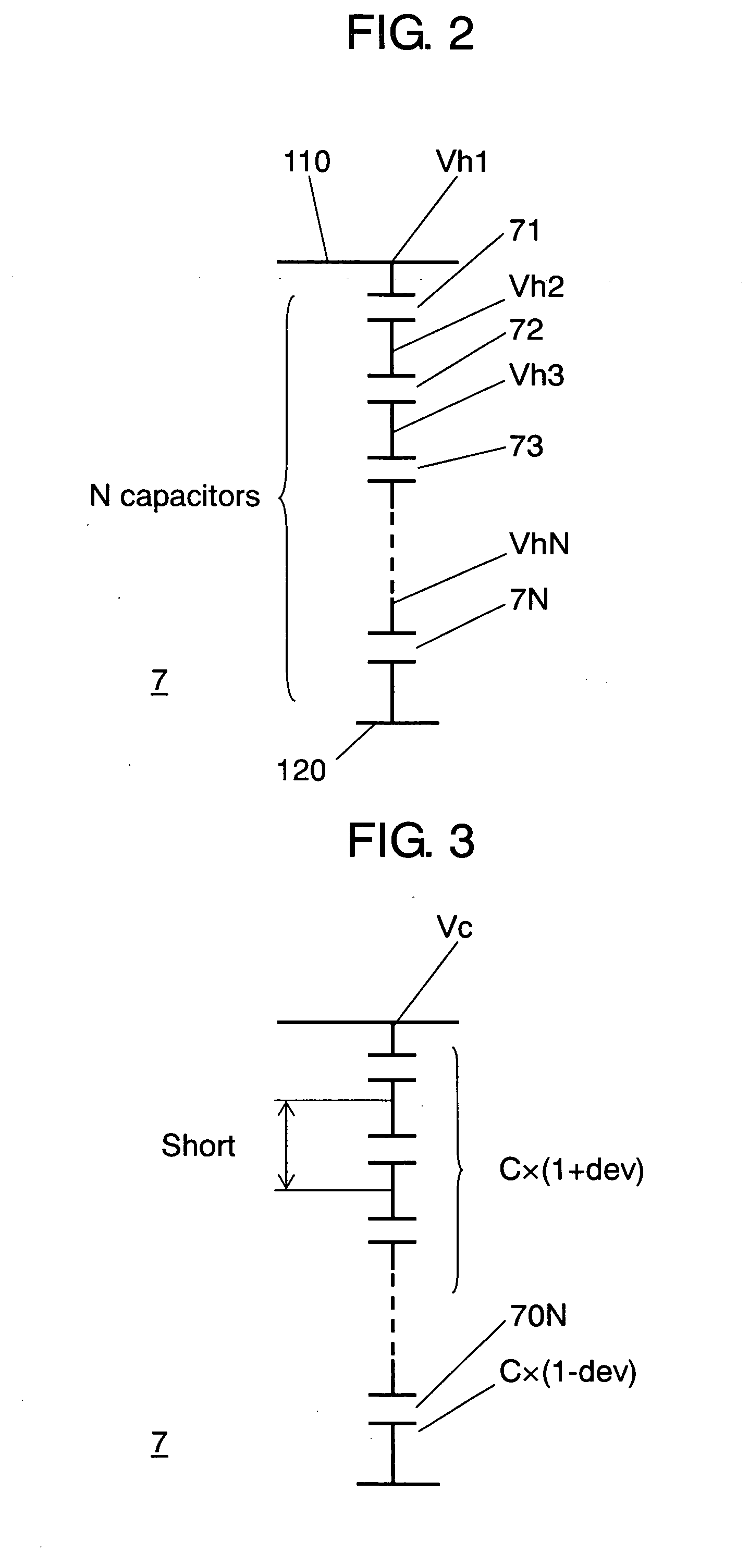
[0012]FIG. 2 is a diagram explaining the voltage on the high potential side of the capacitor unit in accordance ...


PUM


Abstract

A power supply device has a capacitor unit in which capacitors are interconnected in series, a charging unit for charging the capacitor unit at a constant current, a detecting unit for detecting voltage on the high potential side of each of the capacitors, a determining unit for determining the existence of an abnormality based on the voltage detected by the detecting unit. The determining unit determines the abnormality when the difference between respective voltages on the high potential sides of some adjacent capacitors exceeds upper-limit voltage value Va, when the difference is lower than lower-limit voltage value Vb, or when a voltage is negative.

Description

TECHNICAL FIELD[0001]The present invention relates to detection of an abnormality of a capacitor in a power supply device for storing electricity in the capacitor.BACKGROUND ART[0002]A capacitor unit of a large capacity used for storing electricity of the power supply device is generally used for stabilizing a main power supply during load variation. The severest application is usage as a power supply for a backup operation when the main power supply fails. High reliability is required when the capacitor unit is applied to a braking system mounted in a vehicle, for example. For detecting a degradation state of the capacitor unit, a method is known, in which resistance or capacity of the capacitor unit is measured and the degradation state of the capacitor unit during charge is monitored. Additionally, another method is known in which a discharge circuit disposed in parallel with a capacitor disposed in the capacitor unit is operated and the voltage of the capacitor is brought into b...

Claims


Application Information

Patent Timeline
IPC IPC(8): G01R31/312H02J7/00G01R31/00H02J7/02
CPCG01R31/40G01R31/028G01R31/64
Inventor OHASHI, TOSHIHIKOMITANI, YOHSUKEMORITA, KAZUKIODAJIMA, YOSHIMITUTAKEMOTO, JUNJI
Owner PANASONIC CORP
Learn More