Low voltage data transmitting circuit and associated methods

a low-voltage data and transmitting circuit technology, applied in the field of low-voltage data transmitting circuits, can solve the problems of receivers not operating at the desired speed, receivers may not operate at all, and may not interpret the transmitted signal from the transmitter, so as to reduce the chip size, reduce the short-circuit current, and operate stably

Inactive Publication Date: 2008-09-11
SAMSUNG ELECTRONICS CO LTD
View PDF31 Cites 21 Cited by
  • Summary
  • Abstract
  • Description
  • Claims
  • Application Information

AI Technical Summary

Benefits of technology

[0010]It is therefore a separate feature of an embodiment of the invention to provide a method of low voltage data transmitting (LVDT) that may operate stably even when a ground voltage level of a transmitter and a ground voltage level of a receiver are different from each other.
[0011]It is therefore a separate feature of an embodiment of the invention to provide an LVDTC capable of reducing a short-circuit current.
[0012]It is therefore a separate feature of an embodiment of the invention to provide an LVDTC capable of reducing a chip-size and providing matched impedance.
[0013]It is therefore a separate feature of an embodiment of the invention to provide an LVDTC, an LVDTS and / or a method of LVDT that may transmit signals stably when a transmitter and a receiver have different ground levels.
[0014]It is therefore a separate feature of an embodiment of the invention to provide an LVDTC that provides a stable output waveform by reducing short-circuit current that occurs during a switching operation.
[0015]It is therefore a separate feature of an embodiment of the invention to provide an LVDTC that reduces a circuit size and provides a desired termination resistance.

Problems solved by technology

Thus, the receiver may misinterpret a transmitted signal from the transmitter as a result of the voltage difference, and an interface error may occur.
In addition, when a signal level of the transmitter is not recognized by the receiver, the receiver may not operate at a desired speed, or may not operate at all.
Additionally, in the SLVS scheme, a short-circuit current may occur and influence output waveforms during a switching operation.

Method used


Image

  • Low voltage data transmitting circuit and associated methods
  • Low voltage data transmitting circuit and associated methods
  • Low voltage data transmitting circuit and associated methods

Examples


Embodiment Construction

[0045]Korean Patent Application Nos. 2007-0022716, filed on Mar. 8, 2007, and 2007-0115186, filed on Nov. 13, 2007, in the Korean Intellectual Property Office, and entitled: “Low Voltage Data Transmitting Circuit,” are incorporated by reference herein in their entirety.

[0046]Exemplary embodiments will now be described more fully hereinafter with reference to the accompanying drawings; however, they may be embodied in different forms and should not be construed as limited to the embodiments set forth herein. Rather, these embodiments are provided so that this disclosure will be thorough and complete, and will fully convey the scope of the invention to those skilled in the art.

[0047]It will be understood that, although the terms first, second, etc. may be used herein to describe various elements, these elements should not be limited by these terms. These terms are used to distinguish one element from another. For example, a first element could be termed a second element, and, similarl...


PUM


Abstract

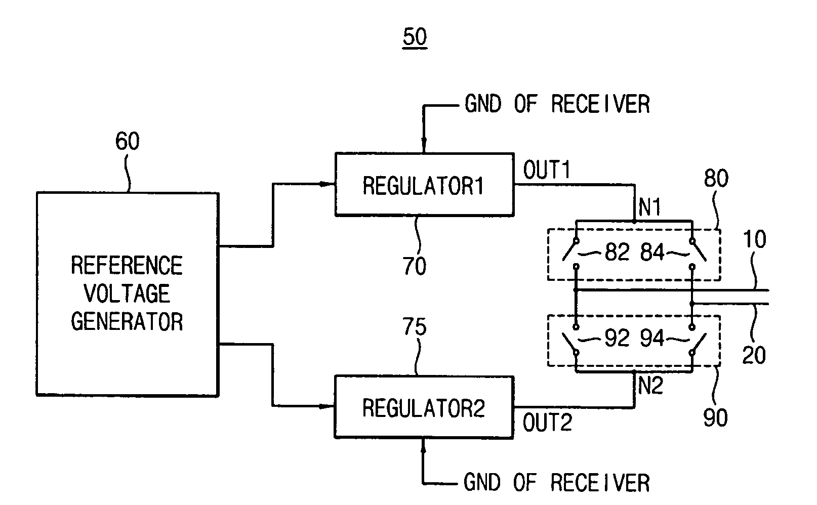
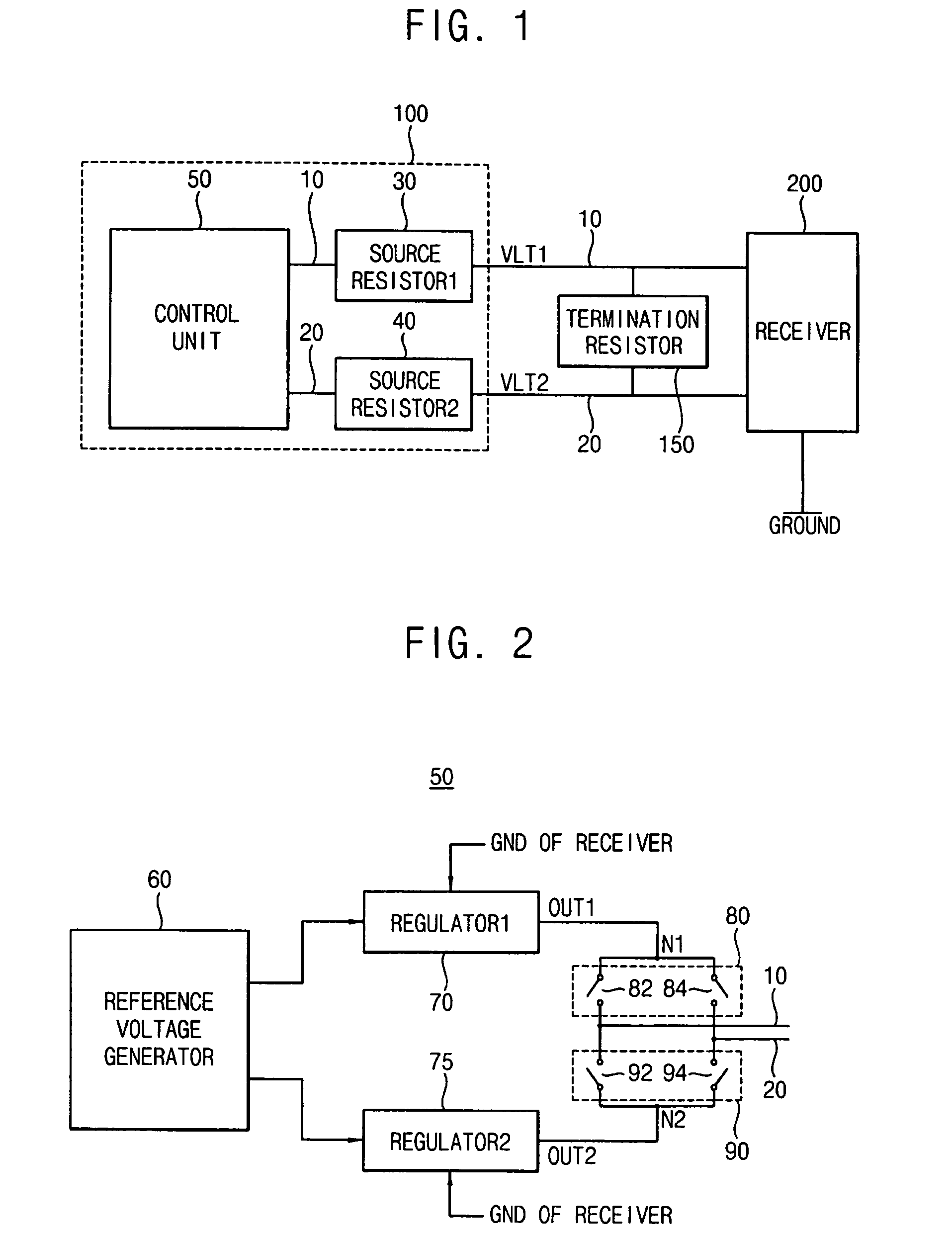
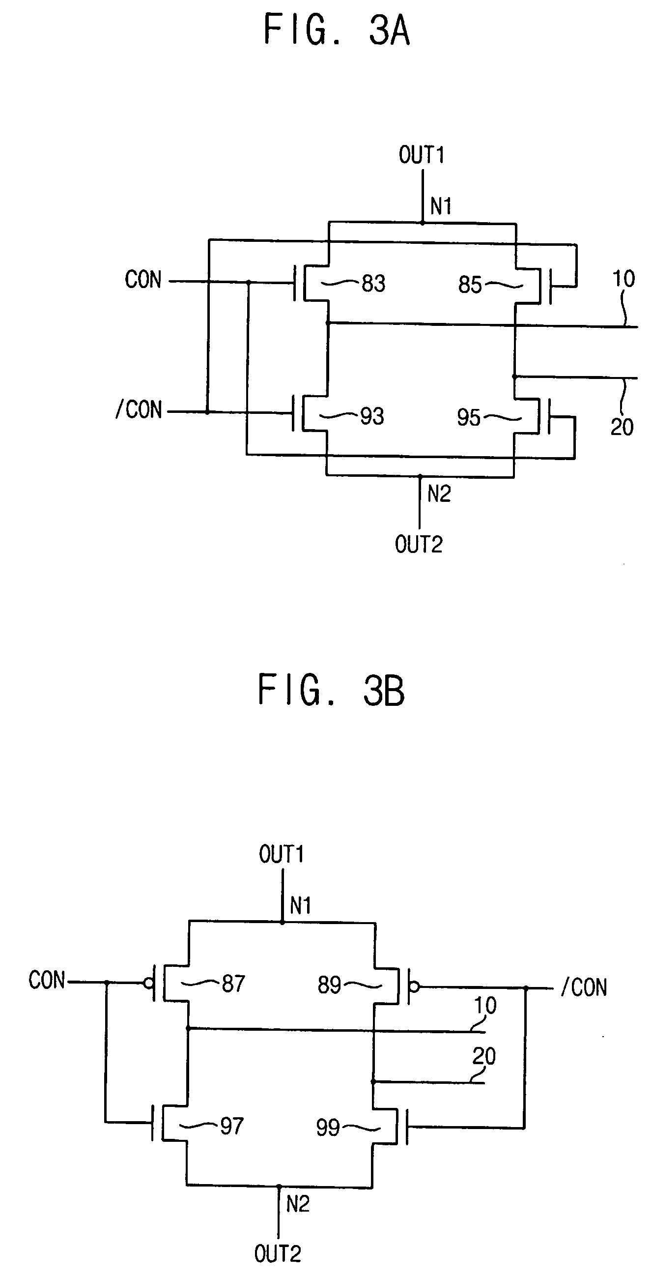
A low voltage data transmitting circuit (LVDTC) may be connected to a first transmission line that transmits a first voltage signal to a receiver and a second transmission line that transmits a second voltage signal to the receiver. The LVDTC includes a first resistor coupled to the first transmission line, a second resistor coupled to the second transmission line, and a control unit coupled to the first transmission line and the second transmission line, the control unit being configured to control voltage levels of the first and second voltage signals such that the voltage levels of the first and second voltage signals are higher than a ground voltage level of the receiver, wherein the first and second voltage signals may constitute a differential pair.

Description

BACKGROUND OF THE INVENTION[0001]1. Field of the Invention[0002]Embodiments relate to a data transmitting circuit and associated methods. More particularly, embodiments relate to a low voltage data transmitting circuit and associated methods.[0003]2. Description of the Related Art[0004]With the explosive growth and usage of the Internet, an amount of data being transmitted in every communication field is increasing. Also, data streams for digital video, HDTV and color graphics require higher bandwidths.[0005]Transmission systems for large amounts of data require new interfacing schemes for high speed data transmission such as a low voltage differential signaling (LVDS) scheme, a reduced swing differential signaling (RSDS) scheme, and a scalable low voltage signaling (SLVS) scheme. These interfacing schemes have characteristics such as a fast bit rate, lower power consumption, and better robustness to noise.[0006]However, in the SLVS scheme, a transmitter and a receiver may have diff...

Claims


Application Information

Patent Timeline
Patent Type & Authority Applications(United States)
IPC IPC(8): H01P5/12
CPCG06F13/4086
Inventor PARK, DONG-UKSEO, JIN-HOPARK, JAE-JIN
Owner SAMSUNG ELECTRONICS CO LTD
Why Eureka
Try Eureka