Ultra Thin Optical Pointing Device and Personal Portable Device Having the Same

a technology of optical pointing and ultra-thin optical strips, which is applied in the direction of portable computers, instruments, computing, etc., can solve the problems of user eye strain, eye strain, and difficulty in using the optical mouse capable of freely performing pointing operations, so as to minimize the malfunction of the optical image sensor, easy to mount, and eliminate discomfort or eye strain

Inactive Publication Date: 2008-09-11
CRUCIALTEC
View PDF7 Cites 57 Cited by
  • Summary
  • Abstract
  • Description
  • Claims
  • Application Information

AI Technical Summary

Benefits of technology

[0042]As described above, the optical pointing device and personal portable device having the optical pointing device according to the present invention is advantageous in that it can eliminate discomfort or eye strain, occurring when light emitted from an infrared LED is radiated to a user's eye.
[0043]Further, the present invention is advantageous in that it can minimize the malfunction of an optical image sensor that may occur when other external light is radiated.
[0044]Further, the present invention is advantageous in that it enables an optical pointing device to be easily mounted in a small-sized portable device such as a mobile phone, thus further increasing the range of applications of the optical pointing device.

Problems solved by technology

In a conventional personal portable device, it has been difficult to use an optical mouse capable of freely performing a pointing operation as in the case of a computer, due to the size and portability thereof.
If light 104 is directly radiated to the user's eye 110 in this way, the user may experience eye strain due to glare, etc., and may suffer a failure of eyesight when the eye is exposed to the light for a long period of time.
Therefore, since light from the red LED is directly radiated to the user's eye, there is a problem in that the user's eyesight fails, or glare occurs, thus causing the user to feel discomfort.
The LED used in an optical pointing device for a mobile phone is a high luminance LED, so that blue, green and white LEDs, as well as the red LED, also cause the same problem.
Meanwhile, since a pointing device, having a shape in which the structure of an optical mouse is scaled down and inverted, has a limitation in thickness, there is a problem in that it is difficult to apply such a pointing device to a thin portable device.
Therefore, similar to FIG. 1, there may occur a problem in which a user easily experiences eye strain or undergoes a failure of eyesight due to glare, etc.
However, in this case, it is only possible to prevent the user's eye from perceiving light radiated from a light source to the user's eye, but it is impossible to solve the problem of the malfunction of an optical image sensor caused by an external light source.
That is, the malfunction of the optical image sensor caused by external ambient light cannot be prevented only by utilizing an infrared LED as a light source.
Therefore, such a structure is the cause of malfunction of the optical image sensor 307.
Such a structure is also the cause of the malfunction of the optical image sensor 413.

Method used


Image

  • Ultra Thin Optical Pointing Device and Personal Portable Device Having the Same
  • Ultra Thin Optical Pointing Device and Personal Portable Device Having the Same
  • Ultra Thin Optical Pointing Device and Personal Portable Device Having the Same

Examples


first embodiment

[0057]FIG. 5 is a diagram of a first embodiment of an optical pointing device according to the present invention, which shows an example in which a lens module, using an infrared LED and an optical plastic material for passing only a wavelength band of infrared rays, radiates infrared rays to a user's eye.

[0058]As shown in FIG. 5, the first embodiment of the present invention provides an optical pointing device 500 including a Printed Circuit Board (PCB) 508; an infrared LED 501 provided on a side of the top surface of the PCB 508 a cover plate 503 for detecting the motion of a finger, which is a subject an illumination system 502 for transmitting light from the infrared LED 501 to the cover plate 503 placed in an upper portion of the optical pointing device an image forming system lens 505 placed below the cover plate 503 and operated to condense light reflected from the subject an optical image sensor 507 for receiving the reflected image of the subject and detecting the motion of...

second embodiment

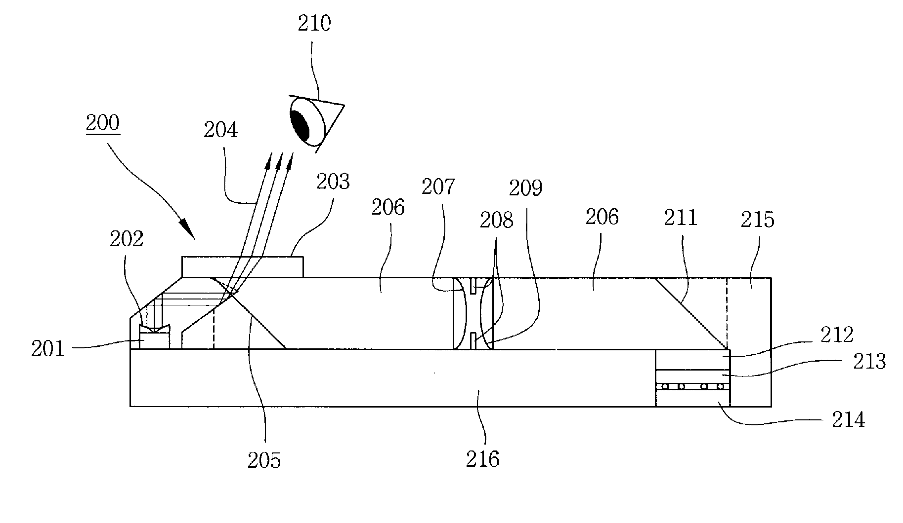
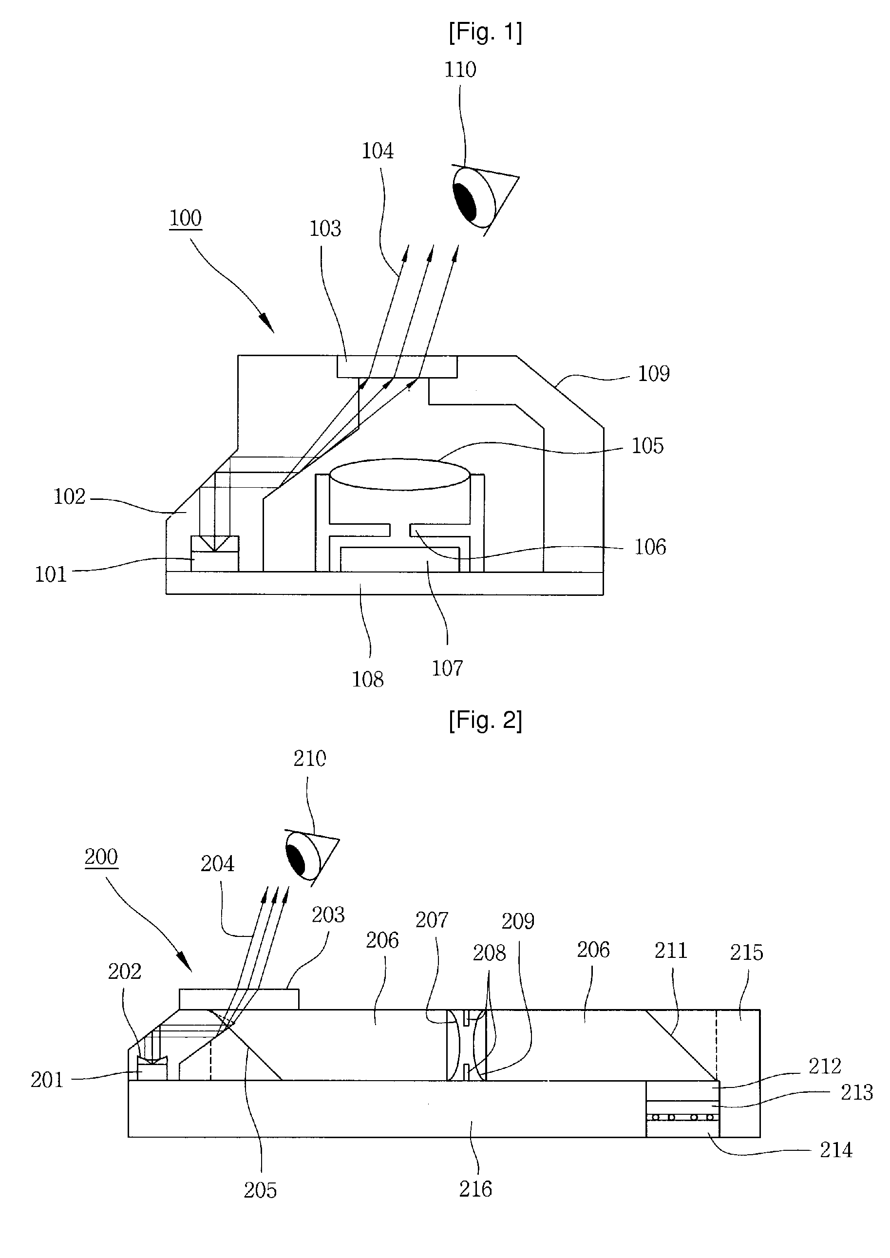
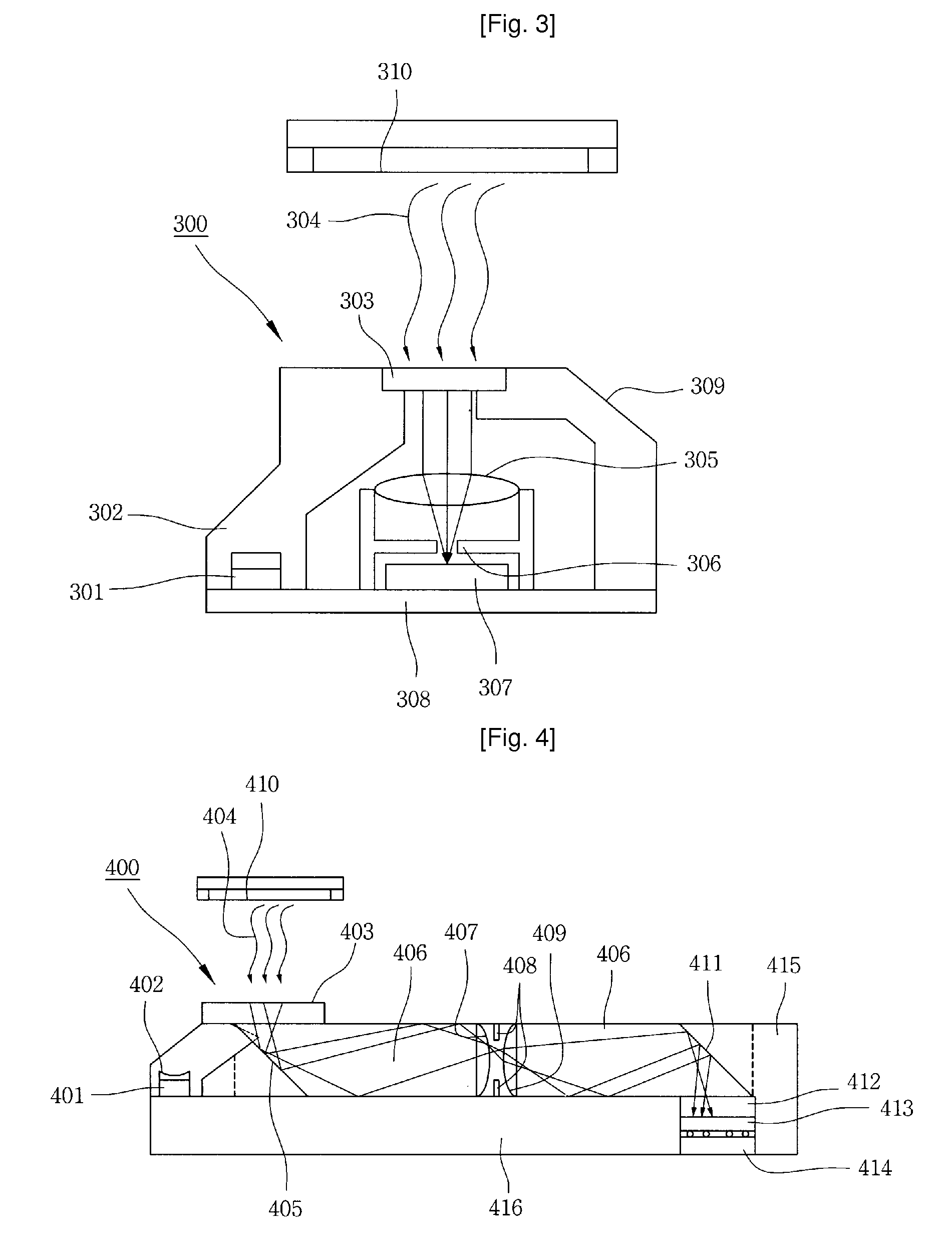
[0062]FIG. 6 is a diagram of a second embodiment of the present invention, which shows an example in which a lens module, using an infrared LED and an optical plastic material for passing only a wavelength band of infrared rays, radiates infrared rays to a user's eye in an optical waveguide planoconvex lens-type ultra thin optical pointing device which changes an optical path to a horizontal direction.

[0063]As shown in FIG. 6, the second embodiment of the present invention provides an optical pointing device 600 including a PCB 616; an infrared LED 601 provided on a side of the top surface of the PCB 616; a cover plate 603 for detecting the motion of a finger, which is a subject an illumination system 602 for transmitting light from the infrared LED 601 to the cover plate 603 placed in an upper portion of the optical pointing device at least one planoconvex lens 606 for changing an optical path to a horizontal direction and an optical image sensor 613 for receiving the reflected ima...

third embodiment

[0067]FIG. 7 is a diagram of a third embodiment of the present invention, which shows an example in which a lens module, using an optical plastic material for passing only a wavelength band of infrared rays, radiates infrared rays to a user's eye in an optical pointing device having a structure in which light from an infrared LED is directly radiated to a cover plate without passing through an illumination system.

[0068]As shown in FIG. 7, the third embodiment of the present invention provides an optical pointing device 700 including a PCB 708; a body tube 709 provided over the PCB 708 an infrared LED 701 placed in a side of an upper portion of the body tube 709; a cover plate 703 for detecting the motion of a finger, which is a subject an image forming system lens 705 placed below the cover plate 703 and operated to condense light reflected from the subject and an optical image sensor 707 for receiving the reflected image of the subject and detecting the motion of the subject, where...


PUM


Abstract

The present invention relates to an ultra thin optical pointing device, and a personal portable device having the optical pointing device. The optical pointing device includes a PCB (508). An infrared LED (501) is provided on a side of the top surface of the PCB. A cover plate (503) detects motion of a finger, which is a subject. An illumination system (502) transmits light from the infrared LED to the cover plate. An image forming system lens (505) is placed below the cover plate to condense reflected light. An optical image sensor (507) receives a reflected image of the subject and detects motion of the subject. A body tube (509) is provided on a side portion over the PCB. The illumination system, the cover plate and the image forming system lens are made of an optical plastic material capable of passing only a wavelength band of infrared rays.

Description

TECHNICAL FIELD[0001]The present invention relates, in general, to an ultra thin optical pointing device using an optical image sensor, and a personal portable device having the ultra thin optical pointing device and, more particularly, to an optical pointing device, which eliminates a user's discomfort caused by glare and prevents malfunction caused by ambient light in an ultra thin optical pointing device used in portable devices such as mobile phones, and to a personal portable device having the optical pointing device.BACKGROUND ART[0002]Currently, personal portable devices can be considered to be in a great turning point toward the improvement of a User Interface (UI). Such a current situation may be compared to the evolution of a computer system from a Disk Operating System (DOS) to a Windows environment.[0003]In a conventional personal portable device, it has been difficult to use an optical mouse capable of freely performing a pointing operation as in the case of a computer,...

Claims


Application Information

Patent Timeline
Patent Type & Authority Applications(United States)
IPC IPC(8): G06F3/00
CPCG06F1/1616G06F3/03547G06F3/0317G06F1/169G06F3/00G06F3/0354
Inventor AHN, KEON-JOONPARK, CHULKIM, JAE-DONGBAE, JAE-HUN
Owner CRUCIALTEC
Why Eureka
Try Eureka