Movable body drive method and movable body drive system, pattern formation method and apparatus, exposure method and apparatus, and device manufacturing method

a technology of movable bodies and drive systems, applied in the direction of photomechanical devices, instruments, printing, etc., can solve the problems of inability to accurately control the position setting of encoders, inability to use position measurement without any correction, and inability to accurately control the position setting. , to achieve the effect of high accuracy and accurate control

Inactive Publication Date: 2008-09-11
NIKON CORP
View PDF77 Cites 124 Cited by
  • Summary
  • Abstract
  • Description
  • Claims
  • Application Information

AI Technical Summary

Benefits of technology

[0013]With this method, position information of the movable body in a predetermined direction parallel to the predetermined plane is measured by using the encoder having a head that irradiates a detection light to a scale having a grating whose periodic direction is the predetermined direction and receives a reflected light from the scale, and the movable body can be driven in the predetermined direction based on the measurement value after correction in which a measurement error caused by the flatness of the scale included in the measurement value of the encoder has been corrected based on information on the flatness of the scale. Accordingly, the movable body can be driven in the predetermined direction with high accuracy using the encoder without being affected by the unevenness of the scale.
[0059]With this apparatus, the position of the movable body can accurately be controlled within a predetermined plane using the encoder system without being affected by a measurement error of the encoder system that occurs due to a formation error of the grating section, and therefore the object mounted on the movable body can be exposed with high accuracy.

Problems solved by technology

Meanwhile, as a measurement apparatus other than the laser interferometer to be used for position measurement of a stage, an encoder can be cited, but because the encoder uses scales and the scales lack mechanical long-term stability (due to drift of scale pitch, fixed position drift, thermal expansion, and the like), and therefore, the encoder suffers from the disadvantages of lacking the linearity of the measurement values and being inferior in the long-term stability, compared with the laser interferometer.
However, in the case position measurement within the moving plane of a wafer stage on which a scale (grating) is arranged is performed using an encoder head, for example, in an exposure apparatus, the accuracy of the grating is similar to that of a movable mirror without bending correction, and therefore from the viewpoint of accuracy, it is obvious that the result of the position measurement without any correction can hardly be used for the position setting.
Moreover, there is the inconvenience that the measurement error of the encoder occurs due to not only the scale (e.g. flatness of the grating surface, or grating formation error) but also a head unit (e.g. gradient of the head, or optical characteristics), a relative displacement of the head and the scale in directions different from a measurement direction in which the encoder measures the position of the wafer stage, or the like.

Method used


Image

  • Movable body drive method and movable body drive system, pattern formation method and apparatus, exposure method and apparatus, and device manufacturing method
  • Movable body drive method and movable body drive system, pattern formation method and apparatus, exposure method and apparatus, and device manufacturing method
  • Movable body drive method and movable body drive system, pattern formation method and apparatus, exposure method and apparatus, and device manufacturing method

Examples


first embodiment

[0098]A first embodiment of the present invention will be described below, with reference to FIGS. 1 to 31.

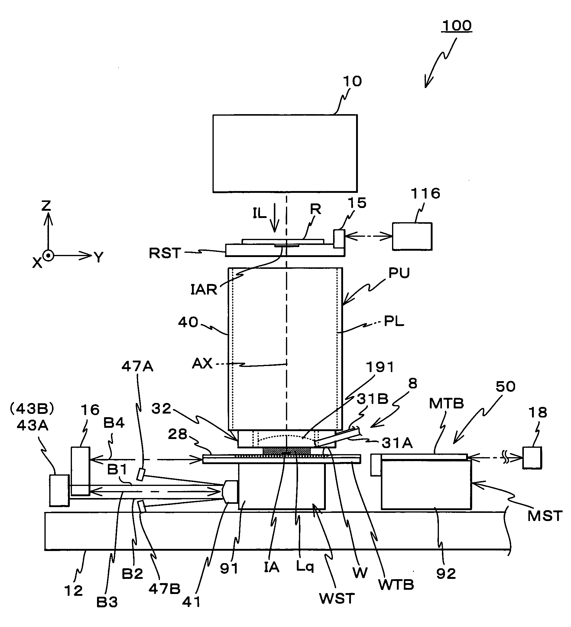
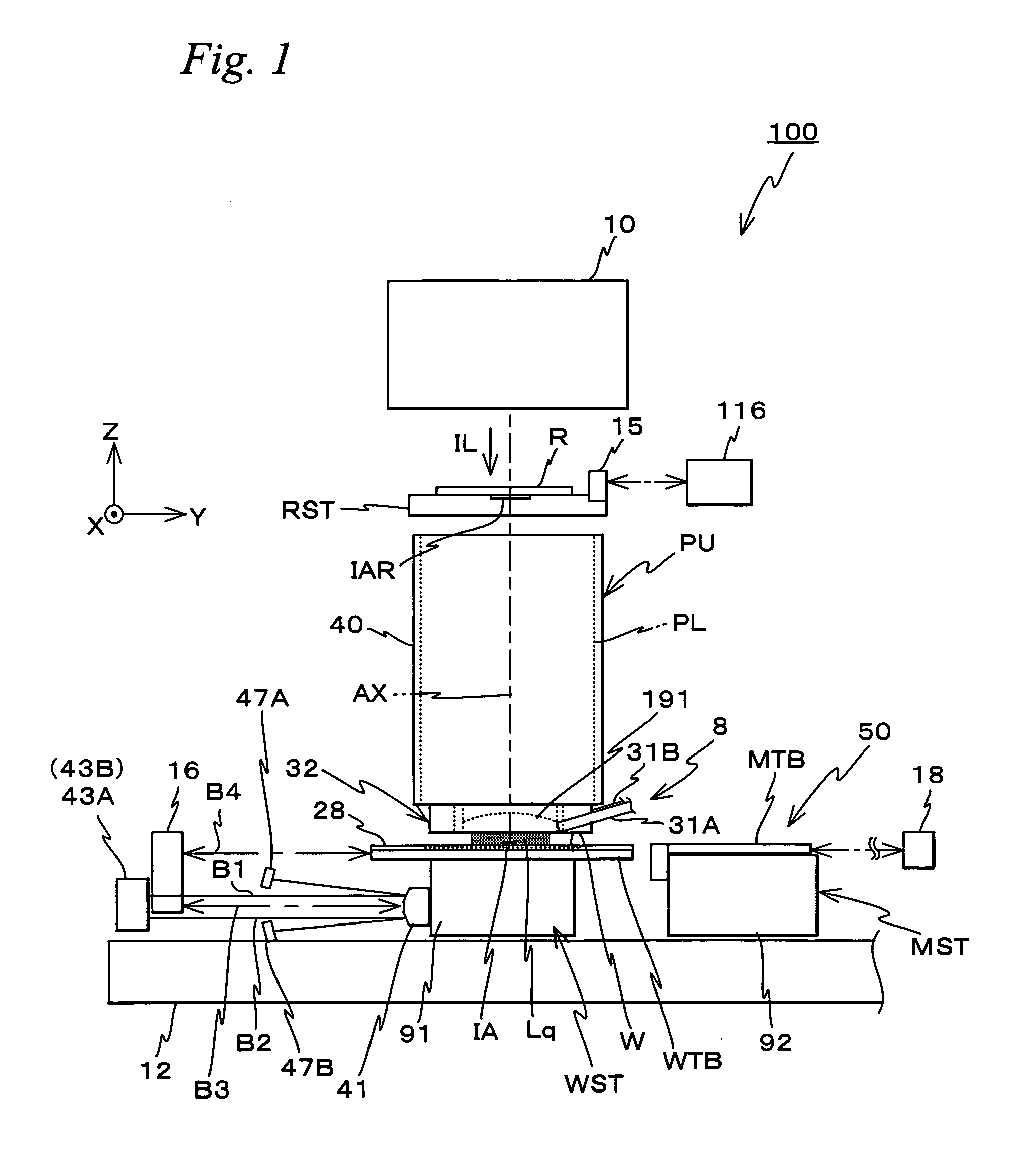
[0099]FIG. 1 schematically shows the configuration of an exposure apparatus 100 related to the first embodiment. Exposure apparatus 100 is a scanning exposure apparatus by a step-and-scan method, that is, a so-called scanner. As will be described later, in the embodiment, a projection optical system PL is arranged, and the following description will be made assuming that a direction parallel to an optical axis AX of projection optical system PL is a Z-axis direction, a direction in which a reticle and a wafer are relatively scanned within a plane orthogonal to the Z-axis direction is a Y-axis direction and a direction that is orthogonal to a Z-axis and a Y-axis is an X-axis direction, and rotation (tilt) directions around the X-axis, the Y-axis and the Z-axis are θx, θy and θz directions respectively.

[0100]Exposure apparatus 100 includes an illumination system 10, a reticle sta...

second embodiment

[0306]Next, a second embodiment of the present invention will be described with reference to FIGS. 32 to 34. The second embodiment is different from the first embodiment described above, only in the operation performed when correction information of grating pitch and correction information of warp of grating lines of the scales are acquired, and the configuration of the apparatus and other operations are similar to those of the first embodiment. Accordingly, the different point will be described below.

[0307]Herein, an acquisition operation of acquiring correction information of grating pitch of the Y scale and correction information of deformation of grating lines (warp of grating lines) of the X scale will be described. Reflection surface 17b is assumed to be an ideal plane, for the sake of simplification of the description.

[0308]First of all, main controller 20 reads the mathematical function z=f1(y) that denotes the unevenness of Y scale 39Y1, the mathematical function z=f2 (Y) t...


PUM

PropertyMeasurementUnit
wavelengthaaaaaaaaaa
angleaaaaaaaaaa
Refractive indexaaaaaaaaaa

Abstract

A drive unit drives a wafer stage in a Y-axis direction based on a measurement value of an encoder that measures position information of the wafer stage in the Y-axis direction and based on information on the flatness of a scale that is measured by the encoder. In this case, the drive unit can drive the wafer stage in a predetermined direction based on a measurement value after correction in which a measurement error caused by the flatness of the scale included in the measurement value of the encoder is corrected based on the information on the flatness of the scale. Accordingly, the wafer stage can be driven with high accuracy in a predetermined direction using the encoder, without being affected by the unevenness of the scale.

Description

CROSS-REFERENCE TO RELATED APPLICATIONS[0001]This non-provisional application claims the benefit of Provisional Application No. 60 / 853,743 filed Oct. 24, 2006, the disclosure of which is hereby incorporated herein by reference in its entirety.BACKGROUND OF THE INVENTION[0002]1. Field of the Invention[0003]The present invention relates to movable body drive methods and movable body drive systems, pattern formation methods and apparatuses, exposure methods and apparatuses, and device manufacturing methods, and more particularly to a movable body drive method and a movable body drive system that drive a movable body within a moving plane, a pattern formation method using the movable body drive method and a pattern formation apparatus equipped with the movable body drive system, an exposure method using the movable body drive method and an exposure apparatus equipped with the movable body drive system, and a device manufacturing method using the pattern formation method.[0004]2. Descrip...

Claims


Application Information

Patent Timeline
Patent Type & Authority Applications(United States)
IPC IPC(8): G03B27/42G03B27/58G01B11/02
CPCG03F7/70516G03F7/70775G03F7/70975Y10T29/49826G03F7/70725Y10T29/49105G03F7/70341Y10T29/49002G03F7/70216G03F7/70716G03F7/70758H01L21/67242H01L21/67703
Inventor SHIBAZAKI, YUICHI
Owner NIKON CORP
Why Eureka
Try Eureka