
Transfer-fixing device, image forming apparatus, and transfer-fixing method

a technology of transfer fixing and image forming apparatus, which is applied in the direction of electrographic process apparatus, instruments, optics, etc., can solve the problems of minute gap formed between the intermediate transfer member and the sheet, faulty image, and surface of the image carrier including resin or rubber may not conform to such irregularities

Inactive Publication Date: 2008-09-11
RICOH KK
View PDF22 Cites 13 Cited by
  • Summary
  • Abstract
  • Description
  • Claims
  • Application Information

AI Technical Summary

Benefits of technology

[0017]This specification further describes a transfer-fixing method according to exemplary embodiments of the present invention. In one exemplary embodiment of the present invention, the transfer-fixing method includes carrying a toner image with an image carrier, pressing a pressing member against the image carrier to form a transfer-fixing nip between the pressing member and the image carrier, heating the toner image carried by the image carrier so that a temperature of the toner image is not higher than Tm +10 degrees centigrade when a toner softening point is Tm degrees centigrade, forming a transfer electrical field at the transfer-fixing nip, and simultaneously transferring and fixing the toner image carried by the image carrier to a transfer material.
[0021]FIG. 3 illustrates yet another related-art transfer-fixing process in which a dotted toner image is transferred from an image carrier with a decreased hardness to a transfer material contacting the image carrier with an increased pressure and fixed to the transfer material;
[0016]This specification further describes an image forming apparatus according to exemplary embodiments of the present invention. In one exemplary embodiment of the present invention, the image forming apparatus includes a transfer-fixing device. The transfer-fixing device transfers a toner image to a transfer material and fixes the toner image on the transfer material, and includes an image carrier, a pressing member, a heater, and an electrical field generator as described above.
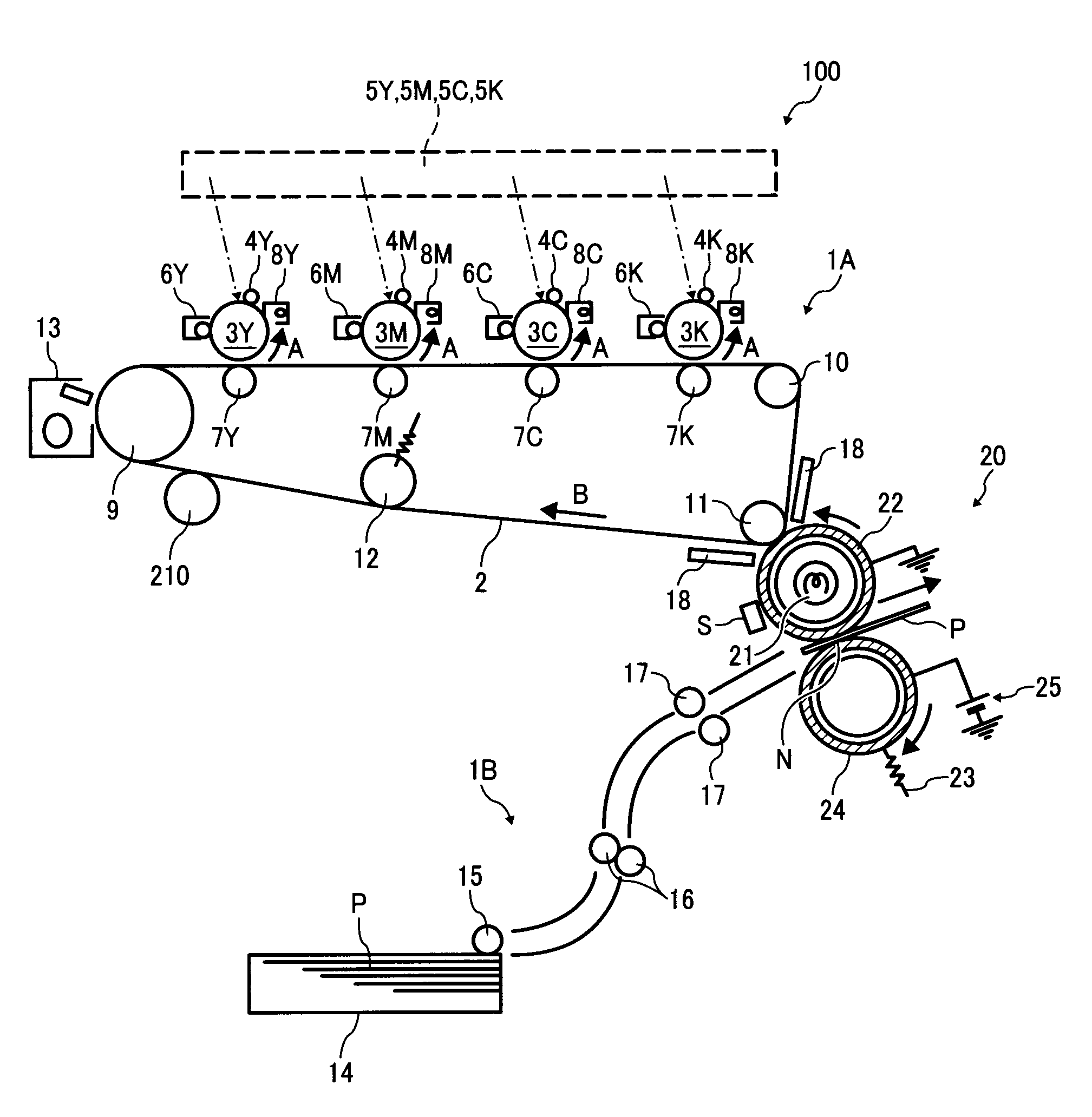
[0038]The heat insulating plates 18 are provided between the intermediate transfer belt 2 and the transfer-fixing roller 22, and prevent heat emission (e.g., heat transfer) from the transfer-fixing roller 22 to the intermediate transfer belt 2. The heat insulating plates 18 include an opening portion in order to prevent heat emission to the intermediate transfer belt 2, so as not to disturb the secondary transfer of the toner image from the intermediate transfer belt 2 to the transfer-fixing roller 22. The heat insulating plates 18 may be provided either in a fixing device (not shown) or in the image forming apparatus 100. The heat insulating plates 18 may include a plate-like material having a metallic luster with low emissivity. In particular, provision of two pieces of metal sheets sandwiching a minute space or a heat insulating material may obtain an improved effect. Alternatively, use of a thin plate including a micro heat pipe structure used for cooling a CPU of a notebook computer may maintain a low temperature of the heat insulating plates 18, thereby preventing heat transfer.
[0033]When the photoconductors 3Y, 3M, 3C, and 3K rotate, the intermediate transfer belt 2 moves. The charger 4Y evenly charges a surface of the photoconductor 3Y and the writer 5Y performs writing based on image information transmitted from the image reader to form an electrostatic latent image on the photoconductor 3Y. The electrostatic latent image is made visible as a toner image by the development device 6Y, which stores yellow toner. The primary transfer device 7Y is applied with a predetermined bias and transfers the toner image on the intermediate transfer belt 2. Similarly, magenta, cyan, and black toner images are formed on the photoconductors 3M, 3C, and 3K, respectively, and transferred and superimposed in this order onto the intermediate transfer belt 2.

Problems solved by technology

However, when a sheet having a rough surface is used, the intermediate transfer member may not fully conform to the surface of the sheet, and consequently a minute gap is formed between the intermediate transfer member and the sheet.
As a result, abnormal electrical discharge occurs at the gap, and the toner image carried by the intermediate transfer member is not properly transferred to the sheet, resulting in a faulty image.
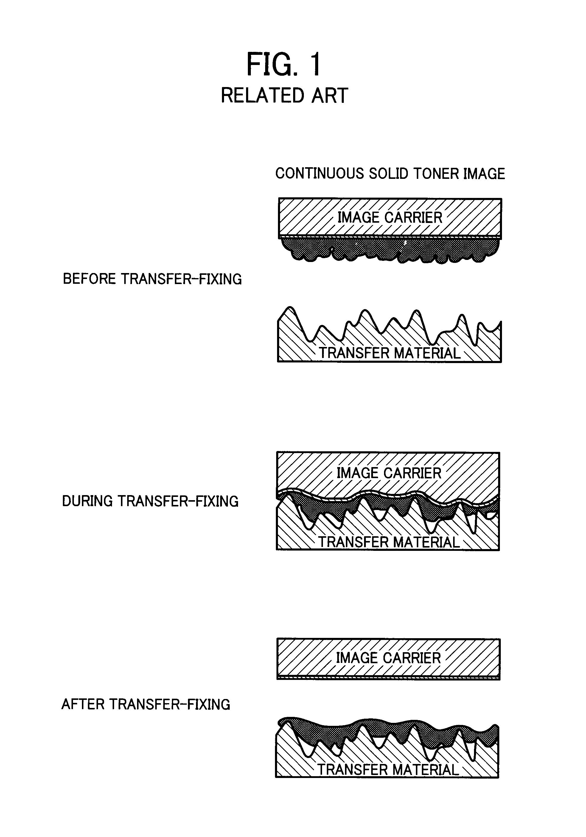
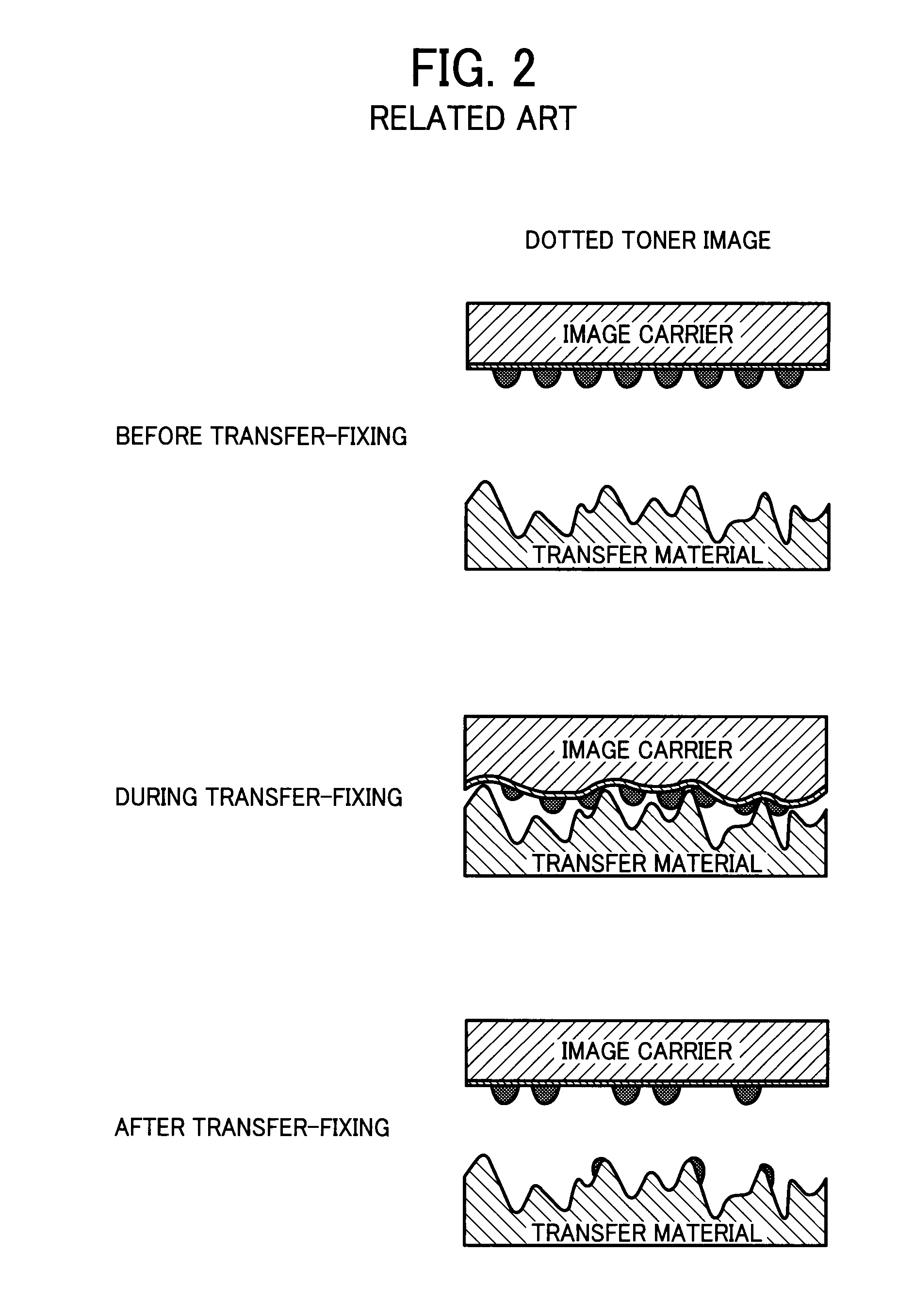
However, since the transfer material (e.g., plain paper) has very small surface irregularities, when the image carrier contacts the transfer material, a surface of the image carrier including resin or rubber may not conform to such irregularities.
Thus, a part of the toner image may fail to contact the transfer material.
As illustrated in FIG. 2, when the toner image includes dots separated from each other, some dots fail to contact the transfer material and thus remain on the image carrier without being transferred to the transfer material, thereby causing an image defect.
Thus, a complete image may not be transferred and fixed to the transfer material.
Thus, if the toner particles fail to contact the transfer material, the toner image may not be transferred to the transfer material, thereby causing an image defect.
As a result, wasted toner may cause environmental burdens, or may shorten a lifetime of a toner removal device.

Method used


Image

  • Transfer-fixing device, image forming apparatus, and transfer-fixing method
  • Transfer-fixing device, image forming apparatus, and transfer-fixing method
  • Transfer-fixing device, image forming apparatus, and transfer-fixing method

Examples


Embodiment Construction

[0027]In describing exemplary embodiments illustrated in the drawings, specific terminology is employed for the sake of clarity. However, the disclosure of this specification is not intended to be limited to the specific terminology so selected, and it is to be understood that each specific element includes all technical equivalents that operate in a similar manner and achieve a similar result.

[0028]Referring now to the drawings, wherein like reference numerals designate identical or corresponding parts throughout the several views, in particular to FIG. 4, an image forming apparatus 100 according to an exemplary embodiment of the present invention is described.

[0029]The image forming apparatus 100 includes an image forming device 1A and a feeding device 1B. The image forming device 1A includes an intermediate transfer belt 2, photoconductors 3Y, 3M, 3C, and 3K, chargers 4Y, 4M, 4C, and 4K, writers 5Y, 5M, 5C, and 5K, development devices 6Y, 6M, 6C, and 6K, primary transfer devices ...


PUM


Abstract

The transfer-fixing device includes an image carrier, a pressing member, a heater, and an electrical field generator. The image carrier carries a toner image. The pressing member presses against the image carrier to form a transfer-fixing nip between the pressing member and the image carrier. The heater heats the toner image carried by the image carrier so that a temperature of the toner image is not higher than Tm +10 degrees centigrade when a toner softening point is Tm degrees centigrade. The electrical field generator forms a transfer electrical field at the transfer-fixing nip.

Description

CROSS-REFERENCE TO RELATED APPLICATION[0001]The present application is based on and claims priority from Japanese Patent Application No. 2007-053849, filed on Mar. 5, 2007 in the Japan Patent Office, the entire contents of which are hereby incorporated herein by reference.BACKGROUND OF THE INVENTION[0002]1. Field of the Invention[0003]Exemplary aspects of the present invention relate to a transfer-fixing device, an image forming apparatus, and a transfer-fixing method, and more particularly, to a transfer-fixing device, an image forming apparatus, and a transfer-fixing method for transferring and fixing a toner image on a transfer material.[0004]2. Description of the Related Art[0005]A related-art image forming apparatus, such as a copier, a facsimile machine, a printer, or a multifunction printer having two or more of copying, printing, scanning, and facsimile functions, forms a toner image on a transfer material (e.g., a sheet) according to image data by electrophotography. For ex...

Claims


Application Information

Patent Timeline
IPC IPC(8): G03G15/16
CPCG03G15/161G03G15/2064G03G15/1605G03G2215/1695G03G2215/2074G03G2215/0129
Inventor KAYAHARA, SHINFUJITA, TAKASHITAKEMOTO, TAKESHITAKAGAKI, HIROMITSUSETO, TAKASHITAMURA, HIROHMI
Owner RICOH KK
Learn More