End mill

a technology of end mills and cutting edges, which is applied in the direction of metal-working equipment, metal-working apparatus, milling equipment, etc., can solve the problems of affecting the life of the tool, reducing the smoothness of the workpiece surface finish produced, and the serrated cutting edge is more prone to mechanical failure, so as to improve the cutting edge and improve the cutting edge. , the effect of improving the cutting edg

Active Publication Date: 2008-09-11
BERKSHIRE PRECISION TOOL
View PDF14 Cites 33 Cited by
  • Summary
  • Abstract
  • Description
  • Claims
  • Application Information

AI Technical Summary

Benefits of technology

[0009]An advantage of the present invention end mill is that the improved cutting edge provided by the edge preparation favorably affects the surface finish of the workpiece produced by the tool.
[0010]Another advantage of the present invention end mill is that the improved cutting edge provided by the edge preparation makes the tool less susceptible to undesirable chatter.
[0011]Another advantage of the present invention end mill is that the improved cutting edge provided by the edge preparation also helps to prevent chipping of the cutting edges and thereby increases the durability of the tool.
[0012]Another advantage provided by the present invention end mill is that improved performance and durability are provided in a cost effective manner. The edge preparation surface(s) of the present invention end mill provides improved performance and durability without incurring the cost of creating a fine surface finish to the entirety of the cutting surface and / or relief wall.
[0013]These and other objects and advantages will become more readily apparent from the more detailed discussion of the preferred embodiment taken in conjunction with the drawings wherein similar elements are identified by like numerals through several views.

Problems solved by technology

It is our experience that such a serrated cutting edge can undesirably influence the performance of an end mill by making it more susceptible to undesirable chatter, and negatively affect the life of the tool by making the cutting edge more prone to mechanical failure; e.g., chipping.
In addition, a serrated cutting edge can also undesirably limit the smoothness of the workpiece surface finish produced by the tool.
Modifying a cutting edge in this manner does not, however, produce a uniform cutting edge and therefore does not resolve the aforesaid performance, durability, and finish issues associated with the cutting edge.

Method used


Image

  • End mill
  • End mill
  • End mill

Examples


Embodiment Construction

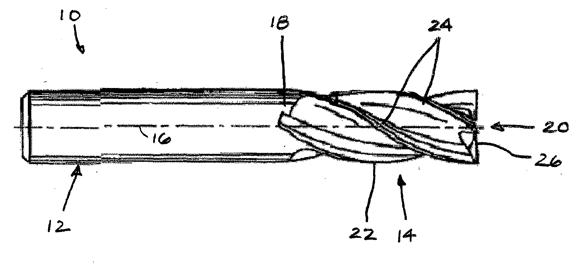
[0025]Now referring to FIG. 1, an end mill 10 is shown that includes a shank section 12 and a fluted section 14, extending along an axis of rotation 16. The shank section 12 is cylindrical and may include one or more grooves cut into its outer surface to facilitate retention of the end mill within the rotary driven apparatus (e.g., a milling machine). Acceptable end mill materials include high strength steel / cobalt, ceramics, carbides, etc.

[0026]The fluted section 14 of the end mill has a first end 18 integrally attached to the shank section 12, a second end 20 (also referred to as the “tip”), and an outer surface 22. A plurality of helical teeth 24 is disposed along the outer surface 22 of the fluted section 14. Each helical tooth 24 includes a tip cutting edge 26 that engages the workpiece when the end mill 10 is plunged into the workpiece. The tip cutting edges 26 are typically disposed at an angle relative to the rotational axis 26 of the end mill 10 to create a relief that faci...


PUM


Abstract

An end mill is provided having an axis of rotation, a shank section and a fluted section, each extending along the axis of rotation, and a plurality of helical teeth. The fluted section has a first end attached to the shank section and a second end. The plurality of helical teeth is disposed within the fluted section. Each helical tooth has a cutting edge, a relief surface, a cutting surface, and an edge preparation surface. The edge preparation surface is contiguous with the cutting edge of the respective tooth.

Description

BACKGROUND OF THE INVENTION[0001]1. Technical Field[0002]The present invention relates to end mills in general, and to end mill cutting edge geometries in particular.[0003]2. Background Information[0004]A conventional end mill operable to remove material from a workpiece typically includes a shank section and a fluted section. The fluted section includes a plurality of helical teeth, each having a cutting surface and a relief wall that intersect with one another to form a cutting edge. The cutting edges of the rotating end mill engage the workpiece and cause “chips” of the workpiece to separate.[0005]The geometry of the helical teeth, and in particular the cutting edge, greatly influences the performance and life of the tool, and the workpiece finish produced by the tool. The cutting edge of a helical tooth has historically been created by grinding the cutting surface and the relief wall of the tooth, leaving a surface finish typically in the range of between eight and sixteen micro...

Claims


Application Information

Patent Timeline
Patent Type & Authority Applications(United States)
IPC IPC(8): B26D1/12
CPCB23C5/10B23C2210/0421B23C2210/0442B23C2210/088B23C2210/123Y10T407/1924B23C2210/44Y10T407/1962Y10T407/1908Y10T407/1946Y10T407/1948B23C2210/126
Inventor FLYNN, CLIFFORD M.
Owner BERKSHIRE PRECISION TOOL
Why Eureka
Try Eureka