
Light-driving system capable of providing signal-measured calibration and a method for performing the same

Active Publication Date: 2008-09-18
MEDIATEK INC
View PDF9 Cites 0 Cited by
  • Summary
  • Abstract
  • Description
  • Claims
  • Application Information

AI Technical Summary

Benefits of technology

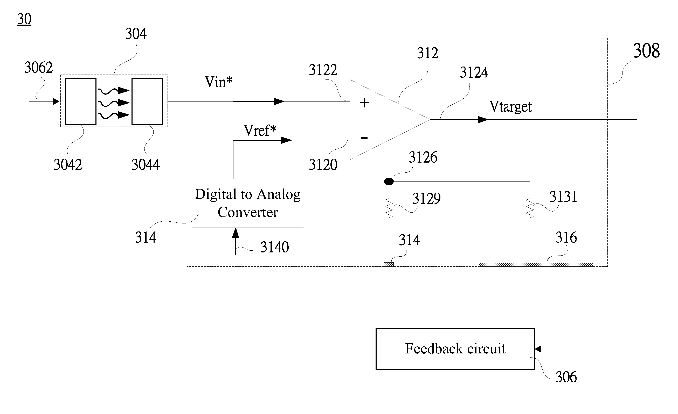
[0013]It is a primary objective of the present invention to provide a light-driving system having an automatic power control (APC) circuit capable of providing an accurate calibration of signal measurement and method for performing the same for increasing a fabricating yield of the system.
[0014]It is a secondary objective of the present invention to provide a light-driving system using which has an automatic power control (APC) circuit disposed with an enlarged-area measured pad than other pad of the prior art for establishing multiple grounding paths to a test instrument thereby raising an accuracy of the signal measurement.
[0035]The present invention utilizes the enlarged-area measured pad than other pad of the prior art, to establish multiple grounding paths access to a test instrument thereby reducing the impedance effect upon the poor contact with the test instrument to achieve an accurate calibration of signal measurement for increasing a fabricating yield of the system.

Problems solved by technology

As known, an impedance effect frequently causes an inaccurate signal measurement for a circuitry system.
This results in a lower chip yield and a higher manufacturing expense during a process of mass manufacture.
Hence, a failure occurs under circumstances, such as an improper contact with the measure pad, will cause a connecting resistance with the probe.

Method used


Image

  • Light-driving system capable of providing signal-measured calibration and a method for performing the same
  • Light-driving system capable of providing signal-measured calibration and a method for performing the same
  • Light-driving system capable of providing signal-measured calibration and a method for performing the same

Examples


Embodiment Construction

[0045]The present invention will now be described more specifically with reference to the following embodiments. It is to be noted that the following description of the preferred embodiments of the present invention are presented herein for purpose of illustration and description only and it is not intended to be exhaustive or to be limited to the precise form disclosed.

[0046]Firstly referring to FIG. 2A, an automatic power control (APC) circuit 208 under test is illustrated according to a first preferred embodiment of the present invention. The automatic power control (APC) circuit 208 under test can be made in form of an integrated circuit (IC) formed on a semiconductor wafer (not shown). As aforementioned, before the APC circuit 208 under test is packaged and electrically connected with other electric components (i.e. a feedback circuit) for constructing a complete light-driving circuitry system, a calibration of a signal measurement of the automatic power control (APC) circuit 2...


PUM


Abstract

This present invention discloses a light-driving system capable of providing an accurate calibration of signal measurement and a method for performing the same, including an automatic power control (APC) circuit which is pre-calibrated for a signal measurement process. By enlarging at least one measured pad of the APC circuit, multiple grounding paths are established via a plurality of probes of a test instrument. An impedance effect predicted on the contact between the probes and the pad is diminished greatly. A voltage value on the pad can be accurately measured. Thus, a reference voltage value input to a first input of a comparator of the APC circuit can be determined on a basis of a specific condition when a ramping voltage value input to a second input of the comparator is substantially equal to a sum of a predetermined reference voltage value and the voltage value of the pad.

Description

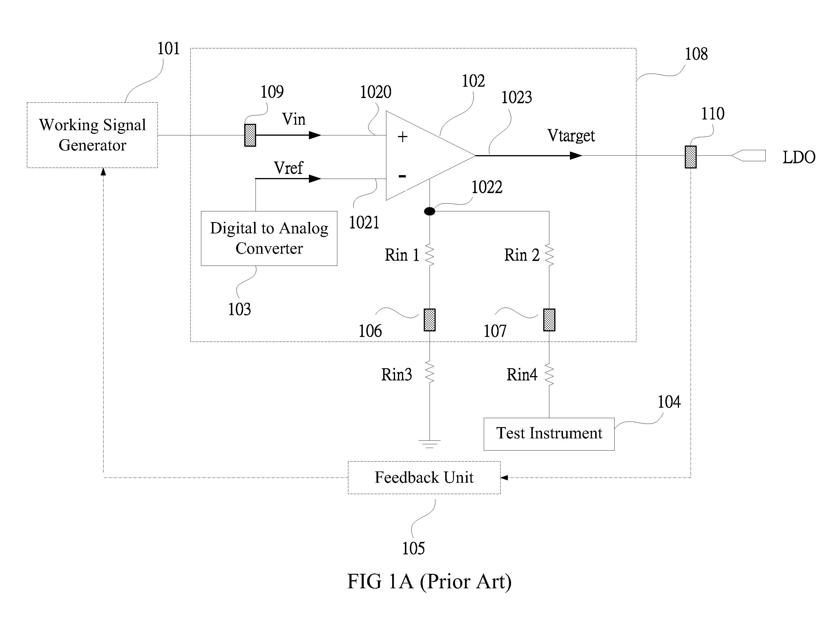
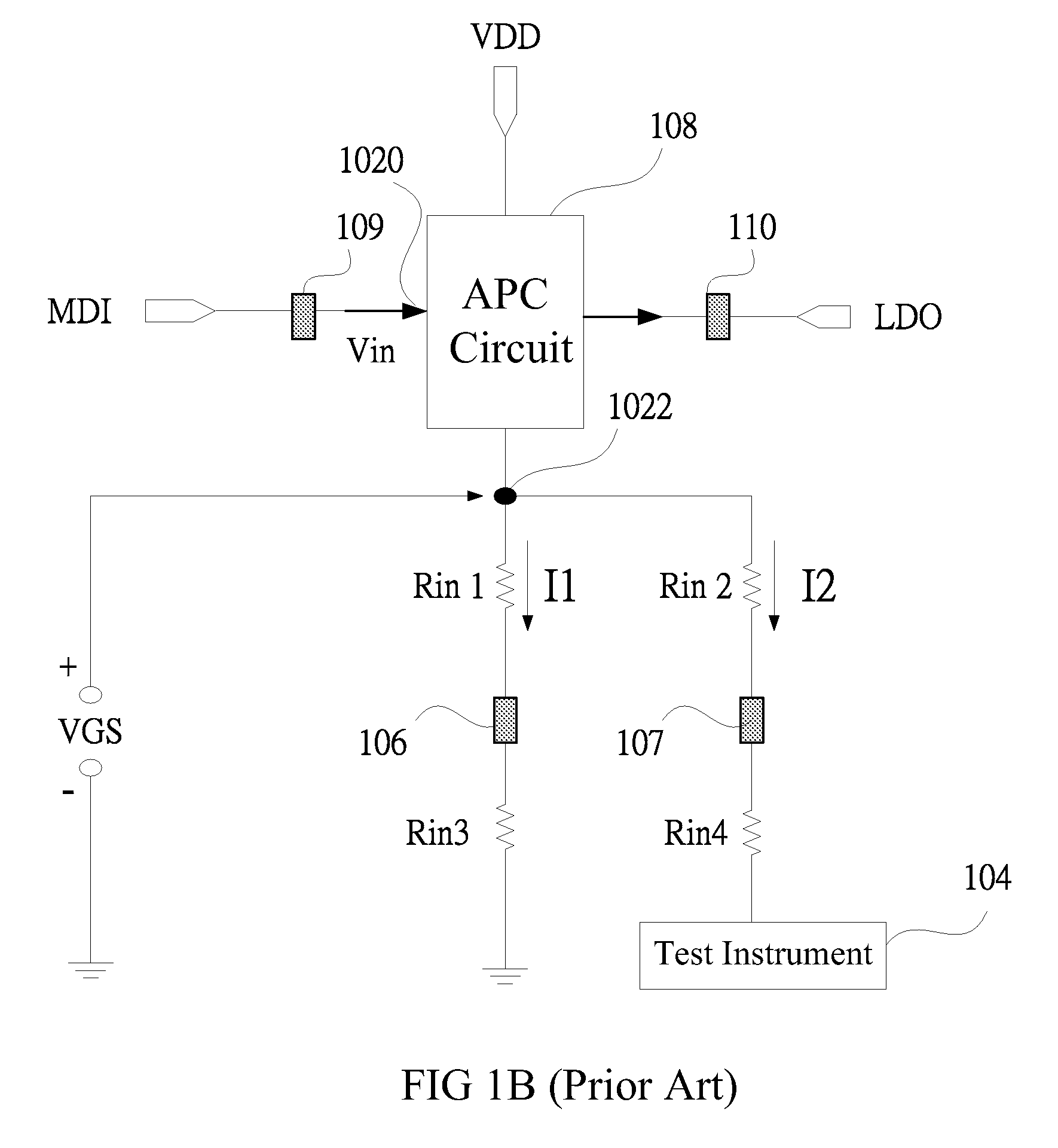
FIELD OF THE INVENTION [0001]The present invention relates to a system and method for performing the same, and more particularly in a light-driving system capable of providing an accurate calibration of signal measurement thereon.BACKGROUND OF THE INVENTION [0002]As known, an impedance effect frequently causes an inaccurate signal measurement for a circuitry system. The impedance effect may be resulted from various factors, including, for instances, an improper measuring operation on testing tool, a hetero-metal junction between the testing tool and a device under test, a circumstance interference, an environmental variation, and so on. Presently, it is regarded as one of the important performance indicators for a circuitry system to provide a capability of accurate calibration of a signal measurement with violation of an impedance effect.[0003]FIG. 1A illustrates a conventional light-driving circuitry system including an automatic power control (APC) circuit 108, a working signal g...

Claims


Application Information

Patent Timeline
IPC IPC(8): G01R31/00G01R27/02
CPCG01R31/2839
Inventor CHANG, AN-NANCHEN, CHIEN-MING
Owner MEDIATEK INC
Learn More