Phase locked loop and method thereof

a phase lock and loop technology, applied in the direction of pulse automatic control, angle modulation details, electrical apparatus, etc., can solve the problems of modulus errors and tradeoffs, and achieve the effect of extending the operation range of the modulator

Active Publication Date: 2008-09-18
UNITED MICROELECTRONICS CORP +1
View PDF5 Cites 21 Cited by
  • Summary
  • Abstract
  • Description
  • Claims
  • Application Information

AI Technical Summary

Benefits of technology

[0011]The present invention is directed to a phase-locked loop (PLL) and a method of generating signals thereof, so as to broaden an operation range of a modulator therein.
[0012]The present invention is directed to a PLL and a method of generating signals thereof, so as to reduce quantization errors.
[0013]The present invention is directed to a PLL and a method of generating signals thereof, so as to reduce modulus of a frequency divider and to further suppress in-band spurs of the PLL.
[0014]The present invention is directed to a PLL and a method of generating signals thereof, so as to reduce spurs of an input signal.
[0017]The present invention further provides an PLL, including a first phase shifter shifting a phase of an input signal; phase detectors, each of which generates a phase difference signal indicating a phase difference between an input signal and a feedback signal and / or the phase difference between the shifted signal and the feedback signal; charge pumps, each of which generates a charge pump output signal indicating the phase differences detected by the phase detectors; a filter transforming the charge pump output signals generated by the charge pumps to a frequency control voltage; a voltage controlled oscillator (VCO) generating an output signal of which the frequency is corresponding to the frequency control voltage; a frequency divider dividing the frequency of the output signal so as to generate the feedback signal; a selecting unit selectively transmitting the feedback signal generated by the frequency divider to the phase detectors; and a modulator, in response to a frequency selecting signal, modulating the feedback signal generated by the frequency divider, and transmitting the modulated result back to the frequency divider so as to reduce quantization errors thereof.

Problems solved by technology

However, a tradeoff is required between a bandwidth range and the capacity of spur suppression.
A disadvantage of the second conventional PLL lies in that the output signal of the frequency divider 206′ does not have 50% duty cycles, and an additional duty cycle correction circuit is necessitated.
Moreover, modulus errors may occur.

Method used


Image

  • Phase locked loop and method thereof
  • Phase locked loop and method thereof
  • Phase locked loop and method thereof

Examples


Embodiment Construction

[0024]In order to make the present invention more comprehensible, embodiments are described below as the examples to prove that the invention can actually be realized.

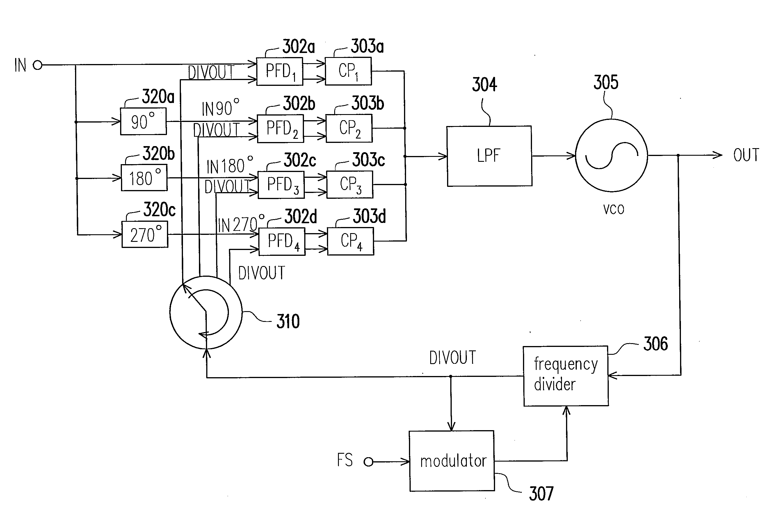
[0025]FIG. 3 is a circuit block diagram depicting a PLL according to one embodiment of the present invention. FIG. 4 is a timing chart depicting signals of the PLL. Please refer to FIG. 3. According to one embodiment of the present invention, the PLL includes phase frequency detectors (PFDs) 302a˜302d, charge pumps (CPs) 303a˜303d, a low-pass filter (LPF) 304, a voltage controlled oscillator (VCO) 305, a frequency divider 306, a modulator 307, a circulator 310, and phase shifters 320a˜320c.

[0026]The phase shifters 320a˜320c shift the phase of an input signal IN. Particularly, the phase shifter 320a performs a 90° phase shift on the input signal IN so as to generate a shifted signal IN90°. The phase shifter 320b performs a 180° phase shift on the input signal IN so as to generate another shifted signal IN180°. The phas...


PUM


Abstract

In a phase locked loop (PLL), phase shifters shift a phase of an input signal. Based on the phases of the input signal, the shifted signals, and a frequency division output signal, phase frequency detectors (PFDs) generate phase difference signals. In response to the phase difference signals, charge pumps (CPs) control output voltages thereof. Based on the output voltages of the CPs, a voltage controlled oscillator (VCO) outputs an output signal. A frequency divider divides the frequency of the output signal from the VCO to generate the frequency division output signal. A circulator outputs the frequency division output signal to one of the PFDs at a proper timing. A modulator reduces quantization errors of the frequency divider.

Description

BACKGROUND OF THE INVENTION[0001]1. Field of Invention[0002]The present invention relates to a phase locked loop (PLL). More particularly, the present invention relates to a PLL employing a plurality of phase frequency detectors (PFDs) and charge pumps (CPs) to accomplish fractional frequency division.[0003]2. Description of Related Art[0004]In communication systems or computer systems, a PLL generates output clock signals having synchronizing rising edges (or falling edges) with an input reference clock signal.[0005]Conventionally, the PLL includes a phase frequency detector (PFD), a charge pump (CP), a low-pass filter (LPF), a voltage controlled oscillator (VCO), and a frequency divider. The PFD compares the phase of an input signal with the phase of a frequency division signal fed back from the frequency divider so as to generate a control signal and provide the same to the CP. In accordance with the control signal, the CP determines if an output voltage of the CP is increased or...

Claims


Application Information

Patent Timeline
Patent Type & Authority Applications(United States)
IPC IPC(8): H03C3/06H03L7/00
CPCH03L7/081H03L7/1976H03L7/087
Inventor CHANG, JEN-CHUNGHSU, CHIA-JUNGLU, SHEY-SHIYANG, YU-CHEWU, TSUNG-CHIENLIN, TZU-CHAO
Owner UNITED MICROELECTRONICS CORP
Why Eureka
Try Eureka