Layered capacitor and mounting structure

a technology of mounting structure and capacitor, which is applied in the direction of capacitors, fixed capacitor details, multiple fixed capacitors, etc., can solve the problem of steep slope of impedance characteristi

Inactive Publication Date: 2008-09-18
MURATA MFG CO LTD
View PDF17 Cites 12 Cited by
  • Summary
  • Abstract
  • Description
  • Claims
  • Application Information

AI Technical Summary

Benefits of technology

[0011]To overcome the problems described above, preferred embodiments of the present invention provide a layered capacitor having a high ESR and a...

Problems solved by technology

However, the layered capacitor described in Japanese Unexamined Patent Application Publication No. 11-204372 has a problem that the slope of the impedance characteristic is steep since the ESR (equivalent series...

Method used


Image

  • Layered capacitor and mounting structure
  • Layered capacitor and mounting structure
  • Layered capacitor and mounting structure

Examples


Embodiment Construction

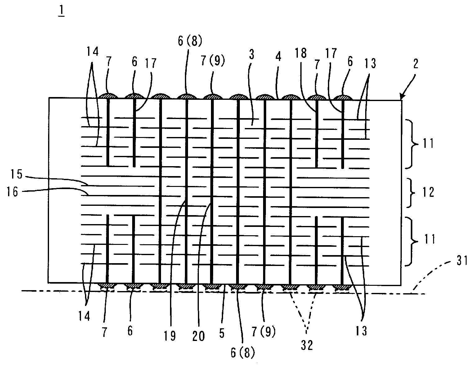
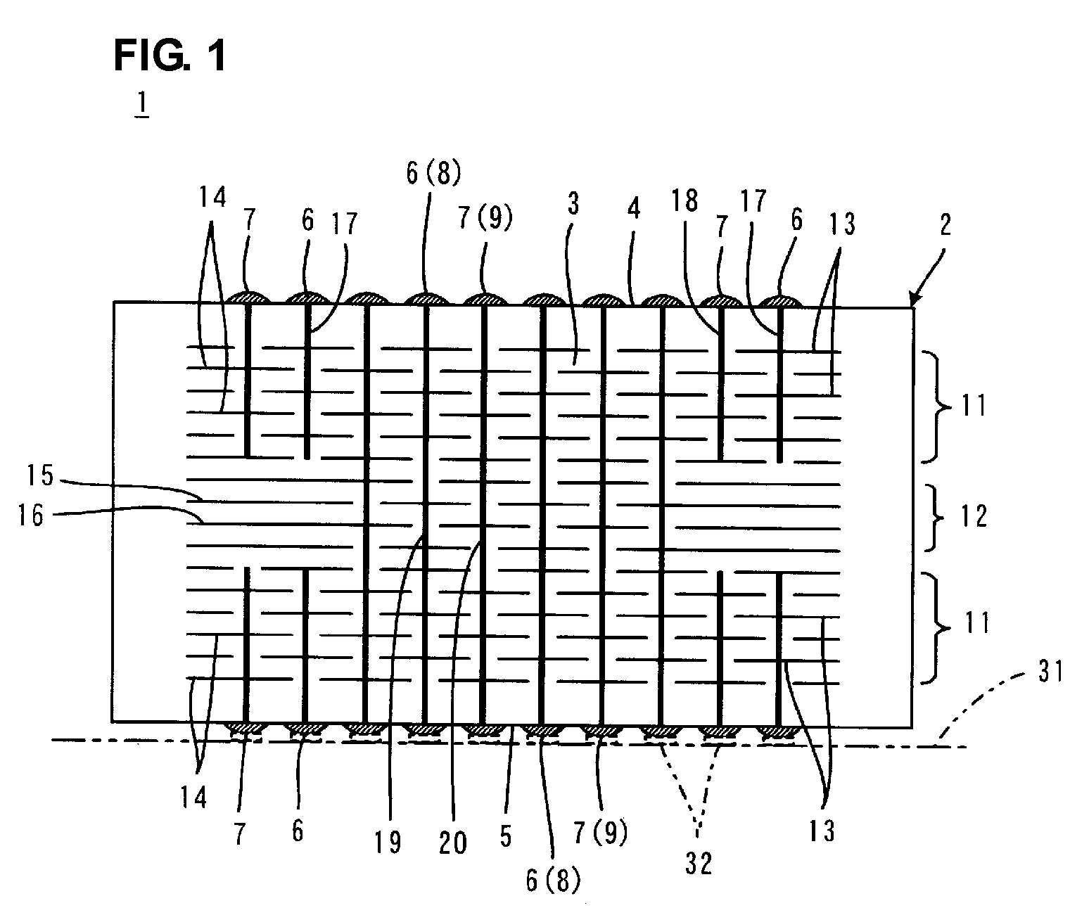
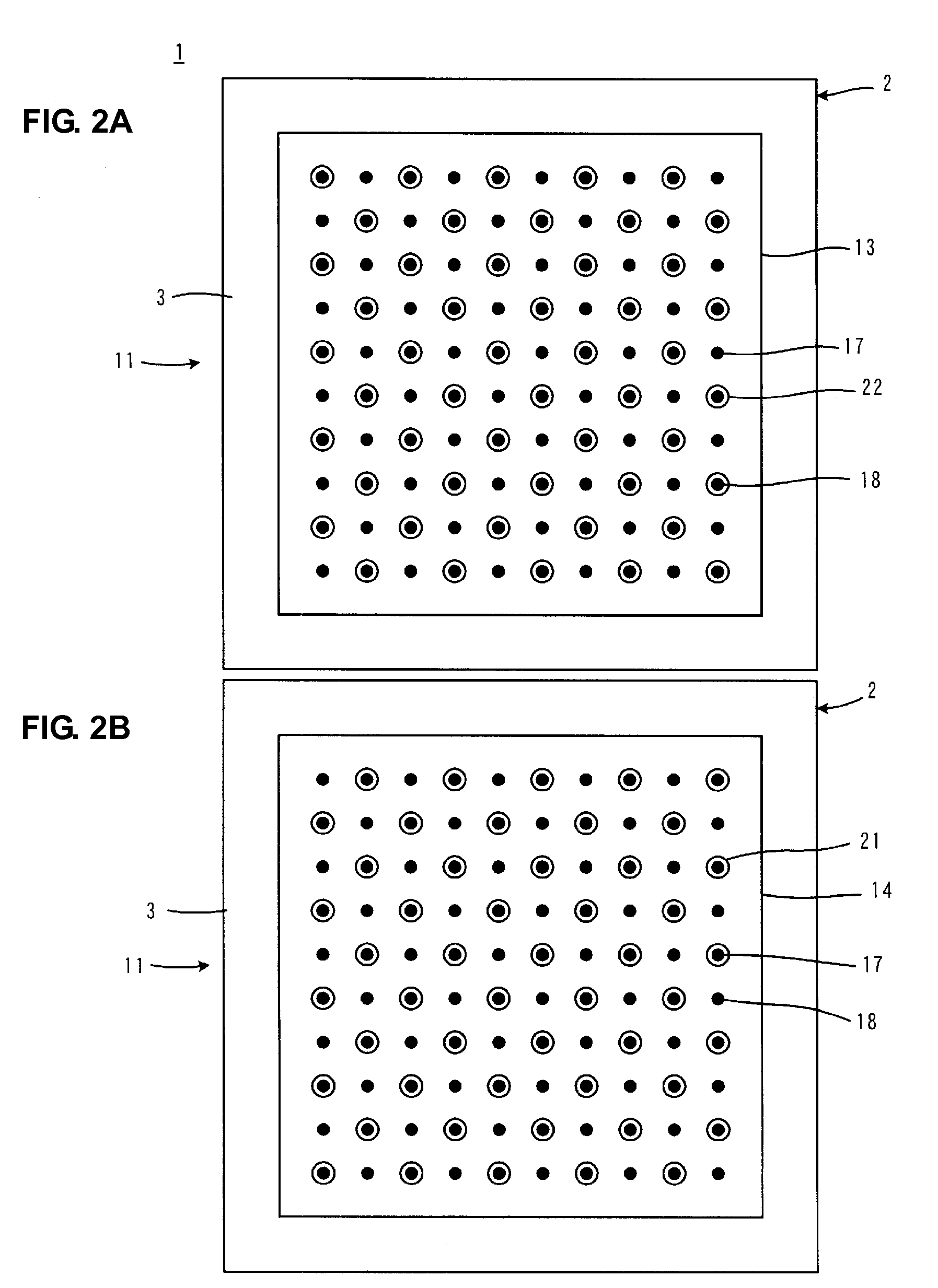
[0033]FIGS. 1 to 3B illustrate a layered capacitor 1 according to a preferred embodiment of the present invention. FIG. 1 is a vertical sectional view illustrating the internal structure of the layered capacitor 1. FIGS. 2A to 3B are horizontal sectional views illustrating the internal structure of the layered capacitor 1.

[0034]The layered capacitor 1 includes a substantially rectangular-parallelepiped capacitor body 2. The capacitor body 2 has a layered structure including stacked dielectric layers 3 composed of, for example, a dielectric ceramic. Bump-shaped first external terminal electrodes 6, second external terminal electrodes 7, third external terminal electrodes 8, and fourth external terminal electrodes 9, for example, are provided on a first main surface 4 and a second main surface 5 of the capacitor body 2. In FIG. 1, the reference numbers 8 and 9 of the third and fourth external terminal electrodes, respectively, are parenthesized since the third external terminal electr...


PUM


Abstract

A layered capacitor includes a capacitor body that is divided into two first capacitor sections and a second capacitor section. The first capacitor sections are disposed at ends in a layer-stacking direction such that the second capacitor section is interposed between the first capacitor sections in the layer-stacking direction. The resonant frequency of the first capacitor sections is greater than that of the second capacitor section. The total number of third internal electrodes and fourth internal electrodes provided per dielectric layer included in the second capacitor section is less than the total number of first via conductors and second via conductors per dielectric layer included in the first capacitor sections. The ESR per dielectric layer included in the second capacitor section is greater than that per dielectric layer included in the first capacitor sections.

Description

BACKGROUND OF THE INVENTION[0001]1. Field of the Invention[0002]The present invention relates to layered capacitors and mounting structures thereof, and in particular, to layered capacitors used in high-frequency circuits and the mounting structures thereof.[0003]2. Description of the Related Art[0004]Layered capacitors having structures described in, for example, Japanese Unexamined Patent Application Publication No. 11-204372 are known as decoupling capacitors used in power supply circuits, for example, for MPUs (microprocessing units) in high-frequency ranges, such as several gigahertz. In such layered capacitors, a large number of via conductors are provided to connect internal electrodes, and the polarities of two adjacent via conductors are opposite to each other. With this, paths of currents flowing from positive electrodes to negative electrodes can be shortened, and flows of the currents can be diversified. Furthermore, since the directions of the currents are opposite to e...

Claims


Application Information

Patent Timeline
IPC IPC(8): H01G4/232
CPCH01G4/232H01G4/38H01G4/30
Inventor TAKASHIMA, HIROKAZUUEOKA, HIROSHITAKAGI, YOSHIKAZU
Owner MURATA MFG CO LTD
Why Eureka
Try Eureka