
Multiplexed optical signal transmission apparatus

a transmission apparatus and optical signal technology, applied in the field of transmission apparatus, can solve the problems of increasing the work amount of maintenance engineers, preventing the network b>15/b> from efficiently accommodating wan lines, etc., and achieve the effect of more flexibly and efficiently accommodating lines in transmission lines

Inactive Publication Date: 2008-09-18
HITACHI LTD
View PDF8 Cites 7 Cited by
  • Summary
  • Abstract
  • Description
  • Claims
  • Application Information

AI Technical Summary

Benefits of technology

[0014]Another problem is that, when a WAN line is added or removed or when the line configuration is changed, the conventional transmission apparatus requires a maintenance engineer to manually perform setting work such as the registration of a device, an interface card, or an optical module. This work not only increases the work amount of the maintenance engineer but also generates a maintenance engineer's error in the operation, setting, and recognition, and this human error sometimes leads to a serious effect on the service. Because of this, there is a strong demand today for a transmission apparatus that has the function for flexibly adapting to various types of WAN lines as well as the function for avoiding operation errors in the maintenance work and for reducing the work amount.
[0017]The present invention allows multiple signals, which have different signal speeds or frame formats, to be accommodated on one interface card, thus accommodating lines more flexibly and efficiently in a transmission line.

Problems solved by technology

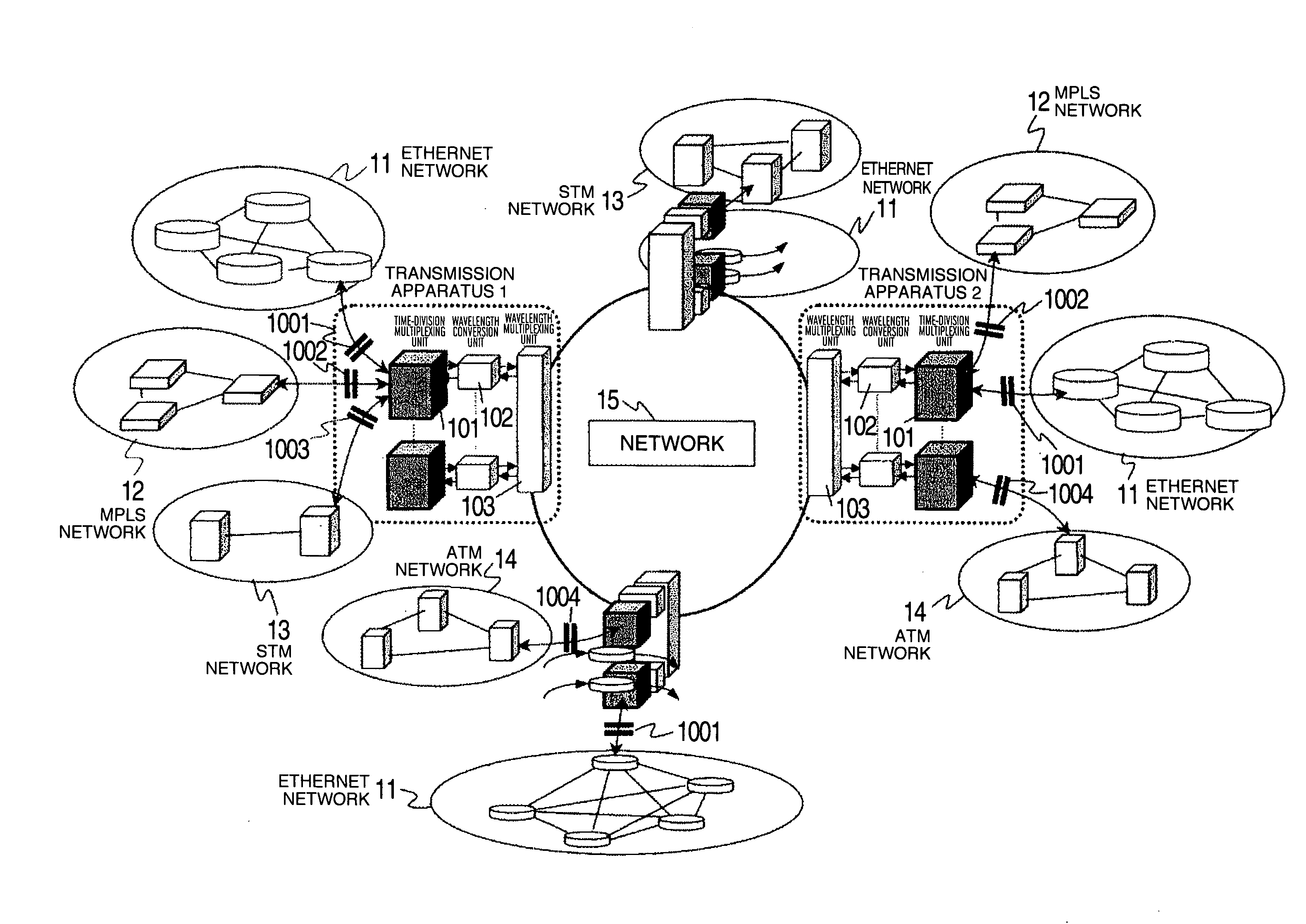
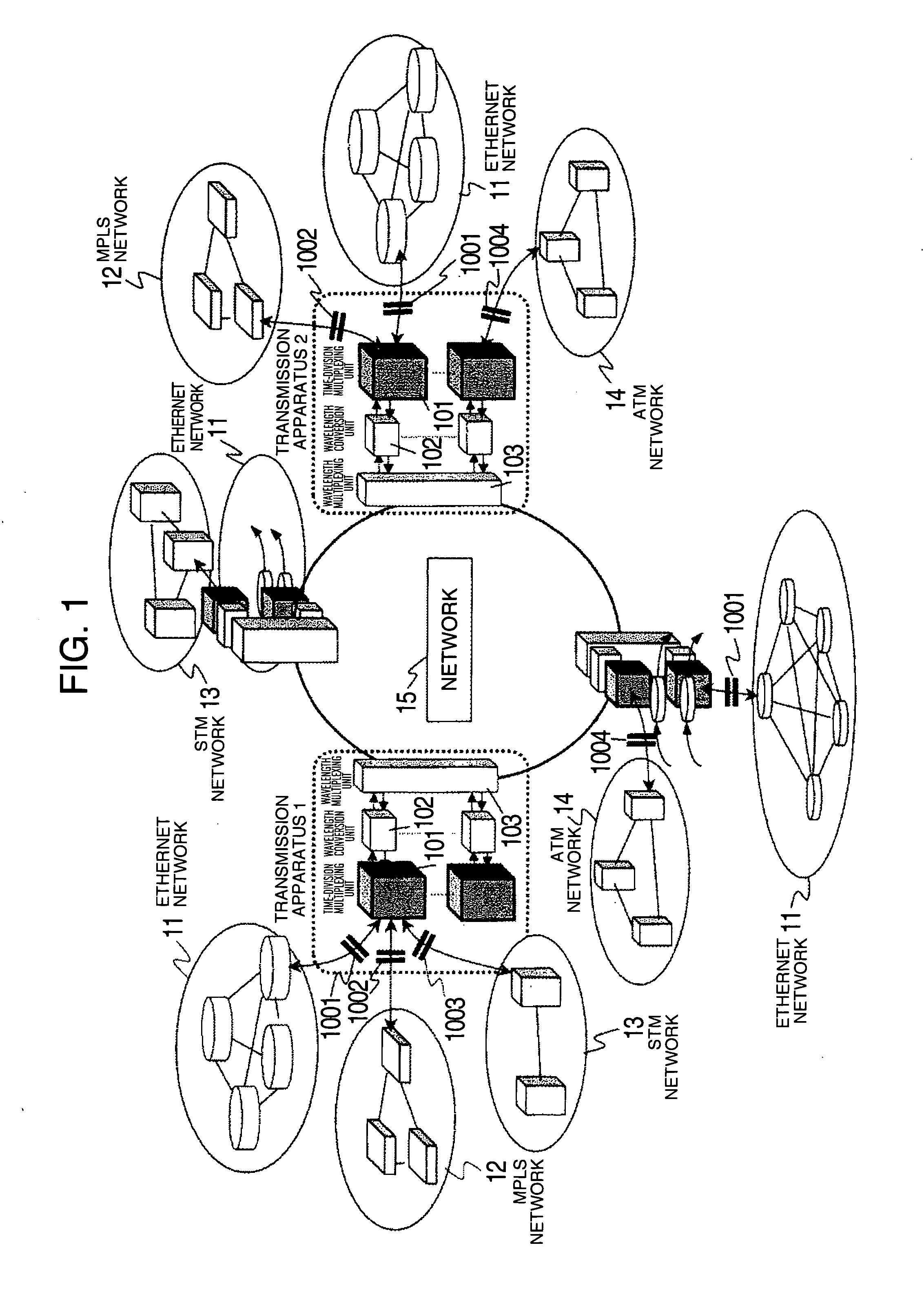
However, preparing the interface cards, one for each signal type, may cause a problem that prevents the network 15 from accommodating WAN lines efficiently.
This problem, in turn, generates a need for a transmission apparatus capable of flexibly adapting to a difference in the optical type, signal speed, or frame format of various WAN line types.
Another problem is that, when a WAN line is added or removed or when the line configuration is changed, the conventional transmission apparatus requires a maintenance engineer to manually perform setting work such as the registration of a device, an interface card, or an optical module.
This work not only increases the work amount of the maintenance engineer but also generates a maintenance engineer's error in the operation, setting, and recognition, and this human error sometimes leads to a serious effect on the service.

Method used


Image

  • Multiplexed optical signal transmission apparatus
  • Multiplexed optical signal transmission apparatus
  • Multiplexed optical signal transmission apparatus

Examples


first embodiment

[0036]FIG. 3 shows the configuration of a transmission apparatus 40 in a first embodiment of the present invention. The transmission apparatus in the first embodiment comprises N optical modules 31-1 to 31-N that receive N low-speed signals 1-N 3000, which have different optical types, signal speeds, or frame formats, from WAN lines as optical signals, convert those optical signals to N electrical signals and send the converted signals to a multi-rate signal processing unit 32 or, conversely, receive N electrical signals from the multi-rate signal processing unit 32, convert the electrical signals to N optical signals, and send the low-speed signals 1-N 3000 to the WAN lines; the multi-rate signal processing unit 32 that can properly process N signals, which have different signal speeds and frame formats, in the multiplexing mode and the de-multiplexing mode independently according to the signal speeds or the frame formats in response to an operation mode setting instruction 3003 fr...

second embodiment

[0063]Although the operation mode selection instruction, optical module type information, signal type information, and bandwidth allocation setting instruction are uniquely determined for one type code in the first embodiment, they cannot be uniquely determined when the type code of an optical module corresponds to two or more signal types. A second embodiment of the present invention is applicable to such a case.

[0064]This embodiment will be described using a transmission apparatus for which an XFP type optical module is used and which has a multi-rate signal processing unit that can accommodate the following three types of signals that have completely different frame formats and signals speeds: STM-64 (signal speed: 9953.28 Mbits / s) defined by ITU-T G.707 and 10GBASE-R (signal speed: 10312.5 Mbits / s) and 10GBASE-W (signal speed: 9953.28 Mbits / s) defined by IEEE802.3.

[0065]FIG. 15 shows the configuration of the transmission apparatus in the second embodiment. For an optical module ...


PUM


Abstract

A transmission apparatus for multiplexing optical signals has a multi-rate signal processing unit that has a plurality of signal processing circuits in advance according to various signal speeds and frame formats and selects a necessary signal processing circuit as necessary. In addition, the transmission apparatus acquires a type code, used to identify the type of the signal of a removable optical module, from the optical module and, from the acquired information, automatically determines the operation mode of the multi-rate signal processing unit, bandwidth allocations according to the signal speeds, and monitoring item contents for different frame formats to eliminate the need for maintenance engineer's work that is otherwise required when a low-speed signal is added.

Description

INCORPORATION BY REFERENCE[0001]The present application claims priority from Japanese application JP2007-064339 filed on Mar. 14, 2007, the content of which is hereby incorporated by reference into this application.BACKGROUND OF THE INVENTION[0002]The present invention relates to a transmission apparatus and a transmission method that multiplex multiple signals, which have different signal speeds or frame formats, into one multiplexed signal which has a predetermined signal speed and, conversely, de-multiplex one multiplexed signal, which has a predetermined signal speed, into multiple signals which have different signal speeds or frame formats.[0003]Recently, broadband lines for connection to the Internet and other networks are widely used in a home, and the line demand oriented toward the IP traffic is increasing. In response to this demand, the services based on high-speed, low-cost Gigabit Ethernet (registered trademark) or 10 Gigabit Ethernet (registered trademark) are rapidly ...

Claims


Application Information

Patent Timeline
Patent Type & Authority Applications(United States)
IPC IPC(8): H04L12/66
CPCH04J3/047H04J2203/0046H04J3/1611
Inventor ATSUMI, TOSHIYUKISHIBASAKI, MASATOSHITAKATORI, KOJITAMURA, YUKIHISA
Owner HITACHI LTD
Learn More