Hydraulically Driven Multicylinder Pumping Machine

a pumping machine and hydraulic drive technology, applied in the direction of pumps, mechanical equipment, flexible wall reciprocating engines, etc., can solve the problems of heavy and costly, displacement organs are subject to frictional wear, and the drive of the machine is not properly isolated from the pumped material, etc., to simplify the machine and achieve simple means of variation and control

Inactive Publication Date: 2008-09-18
GARNIMAN
View PDF24 Cites 17 Cited by
  • Summary
  • Abstract
  • Description
  • Claims
  • Application Information

AI Technical Summary

Benefits of technology

[0008]The new pumping machine is directly driven by a hydraulic pump drive, greatly simplifying the machine and providing simple means of variation and control of the flow of the pumped fluid delivered. Moreover, the double diaphragm arrangement provides a double protection of the pumped fluid from the pumping fluid.

Problems solved by technology

However such displacement organs are subject to frictional wear and the drive of the machine is not properly isolated from the pumped material.
However the membranes of these known membrane pumps are driven by a crankshaft mechanism which especially in large machines is heavy and costly and requires pulsation dampening.
However, none of the cited pump diaphragm systems possesses the advantage of a double protection of the pumped fluid from the pumping fluid, and none are adapted for multicylinder arrangements.

Method used


Image

  • Hydraulically Driven Multicylinder Pumping Machine
  • Hydraulically Driven Multicylinder Pumping Machine
  • Hydraulically Driven Multicylinder Pumping Machine

Examples


Embodiment Construction

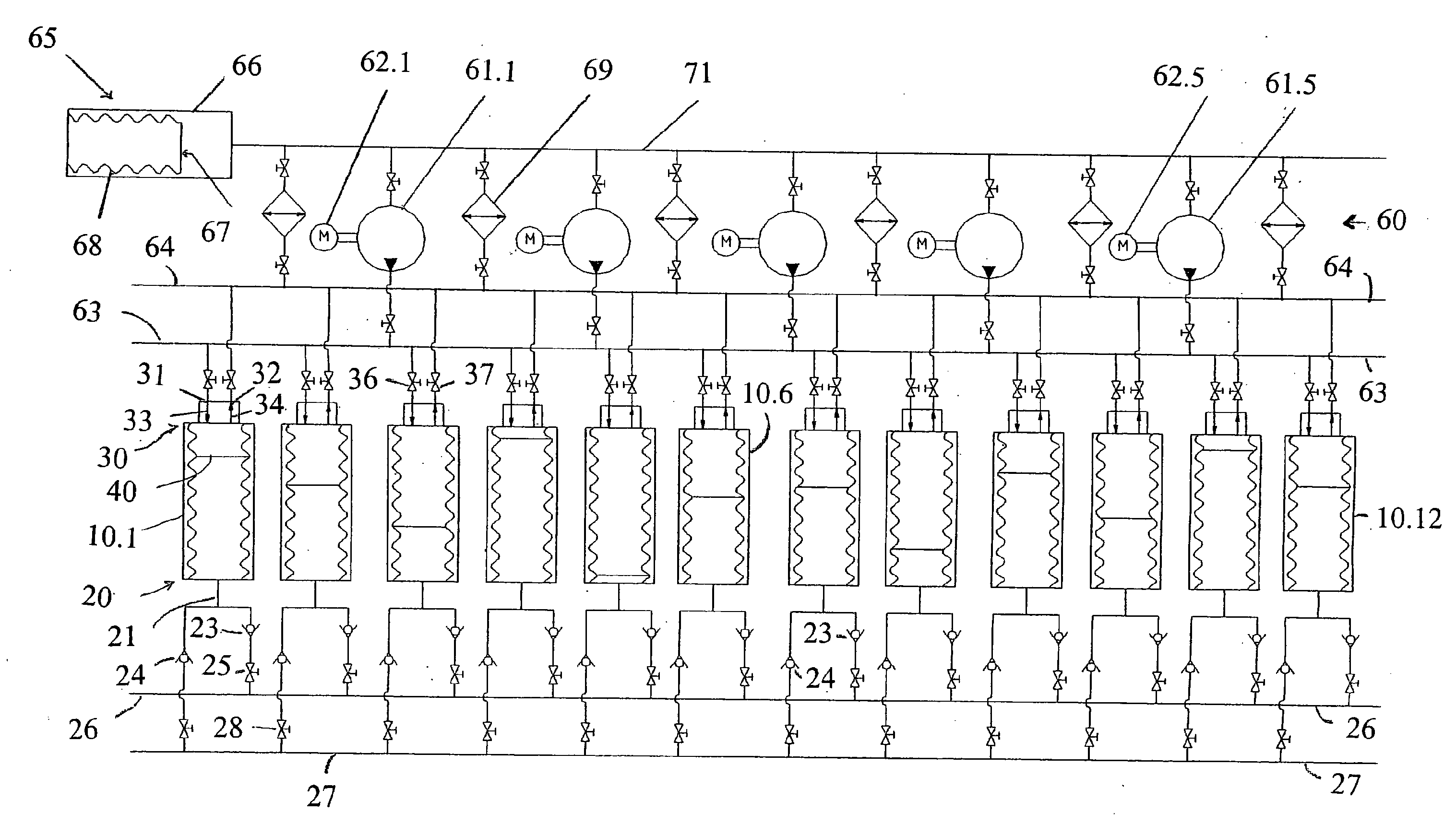
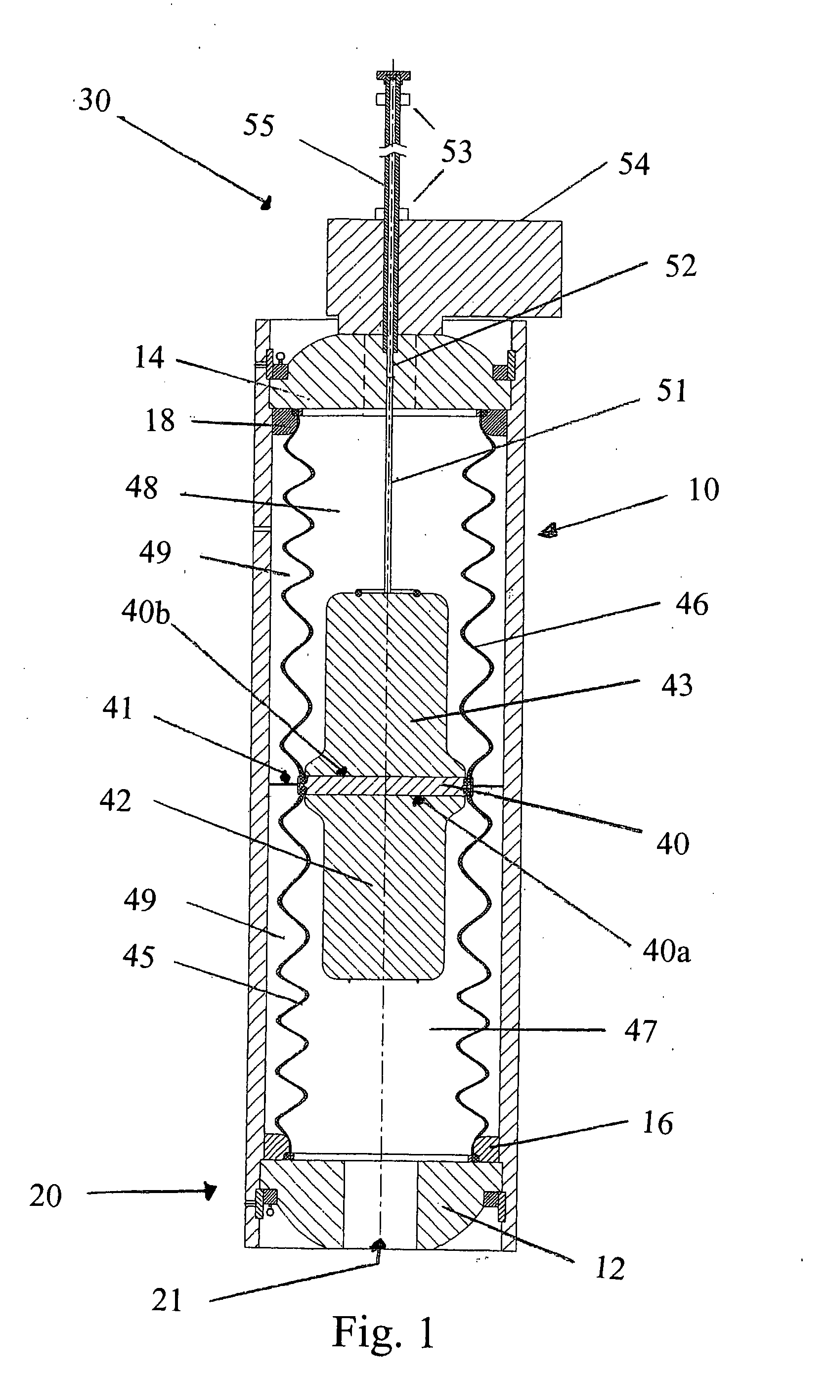
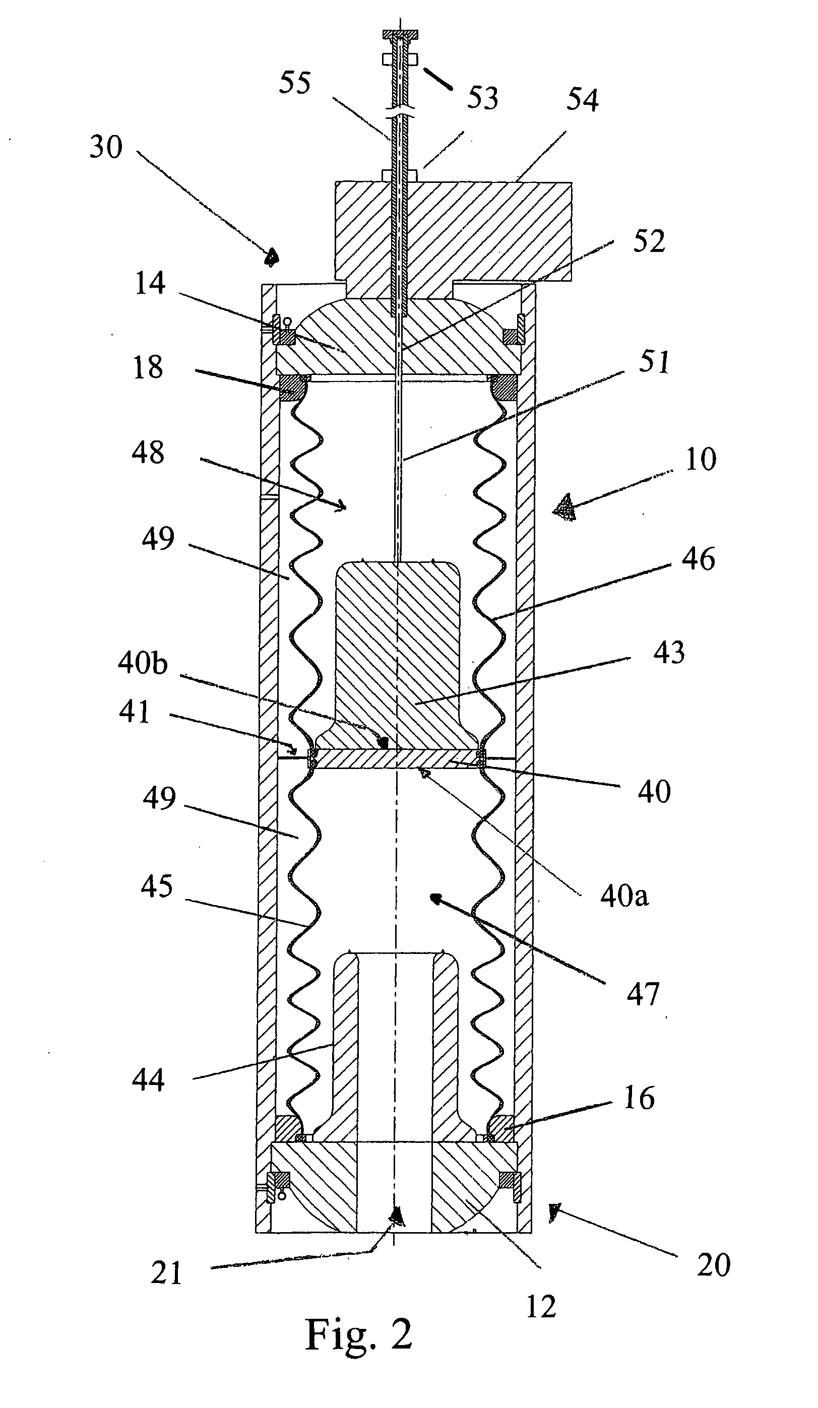
[0017]The pumping machine whose layout is illustrated in FIG. 3 is composed in this example of twelve pressure resistant steel cylinders 10.1-10.12 containing each a non-conventional double membrane displacement device shown in detail in FIG. 1 and in a varied form in FIG. 2. All the cylinders 10.1-10.12 work in parallel and their forward (pumping) stroke is driven by hydraulic oil under pressure coming via a hydraulic circuit 60 from one or more hydraulic pumps 61.1-61.5, five such hydraulic pumps being shown, each powered by an electric motor 62.1-62.5, and connected in parallel with heat exchangers 69 for cooling the hydraulic oil. The hydraulic circuit 60 includes oil intake and outlet manifolds 63,64 and a pump's cooled oil manifold 71.

[0018]The pump cylinders 10 each have a first or bottom end 20 with a combined first inlet and outlet 21 for fluid to be pumped and a second or upper end 30 with a second inlet 31 and a separate second outlet 32 for hydraulic oil. The inlet / outle...


PUM


Abstract

A hydraulically driven multicylinder diaphragm pumping machine for pumping difficult-to-pump materials comprises pump cylinders each having at one end (20) an inlet / outlet (21) for fluid material to be pumped supplied under adjustable pneumatic pressure, and at the other end (30) an inlet and outlet (31,32) for hydraulic oil. A separator (40) movable to-and-fro inside the pump cylinder (10) is connected to the fluid-material end of the cylinder by a bellows-like flexible diaphragm (45) and to the fluid material end (30) by another bellows-like diaphragm (46) leaving an outer annular space (49) that contains hydraulic fluid. The total volume of pumping hydraulic oil in the cylinders (10.1-10.12) is maintained constant and equal to ½ the total displacement volume of the cylinders by a device (65) that compensates for thermal expansion and controls the necessary return flow of hydraulic oil for driving the pump. The separators (40) move with an intake stroke at constant speed for all cylinders, and with pumping strokes function of the hydraulic oil delivery, so a lesser number of separators (40) effect an intake stroke while a greater number of separators (40) effect a discharge stroke.

Description

[0001]FIELD OF THE INVENTION[0002]The invention relates to hydraulically driven multicylinder diaphragm pumping machines, in particular for pumping difficult-to-pump fluid materials, like minerals, ores, sludges, suspensions, slurries, and gels, and to methods of operating such pumping machines. These pumping machines may be referred to herein simply as pumps or machines.BACKGROUND OF THE INVENTION[0003]Conventional pumping machines that can be used for difficult-to-pump materials have displacement organs such as pistons, plungers, peristaltic hoses etc. However such displacement organs are subject to frictional wear and the drive of the machine is not properly isolated from the pumped material.[0004]Pumps with flat or tubular diaphragms are known. A pump of the flat membrane type is commercialized by Geho. The tubular diaphragm pump is described as an improvement over the flat membrane type. One example of a tubular diaphragm pump is described in patent specification GB 2161221. Th...

Claims


Application Information

Patent Timeline
Patent Type & Authority Applications(United States)
IPC IPC(8): F04B43/113F16J3/06F01B19/04F04B49/12F04B49/00F04B43/10
CPCF04B43/1136F04B43/113
Inventor EYSYMONTT, JAN
Owner GARNIMAN
Why Eureka
Try Eureka