
Telecommunication system used with a means for transporting passengers and cargo

a technology of telecommunication system and passenger, applied in the field of telecommunication system, can solve the problems of inability of registration system to distinguish whether a mobile device is inside or outside a vehicle, inability to carry passengers, and inability to carry mobile devices, etc., to suppress the increase in hardware resources and power consumption of a wireless network, and increase the process load on the base station

Inactive Publication Date: 2008-09-18
FUJITSU LTD
View PDF10 Cites 36 Cited by
  • Summary
  • Abstract
  • Description
  • Claims
  • Application Information

AI Technical Summary

Benefits of technology

[0014]The present invention is configured such that wireless telecom apparatuses used by passengers on-board a vehicle are not required to individually access a base station; thereby eliminating the possibility of an increased process load on the base station when many mobile devices simultaneously carry out handoffs and / or changeovers. That is, it is configured to have an on-transportation means access point to consolidate telecommunications from individual passenger's wireless telecom apparatuses while on-board a vehicle, and then access an external wireless network; thereby making it possible to suppress increases in hardware resources and power consumption on a wireless network.

Problems solved by technology

In the current location registration system, congestion of a radio environment occurs when a plurality of mobile devices, that are traveling in a vehicle, carry out individual location registrations for a network (e.g., congestion occurs when an electric train or bus moves across location registration areas.)
In order to accomplish a NEMO, it is necessary to determine whether a mobile device is inside a vehicle or outside of a vehicle; however, the conventional location registration system is not capable of distinguishing whether a mobile device is inside or outside of a vehicle.
An other problem is that power consumption is the same when a mobile device is used outdoors as it is when it is used indoors.

Method used


Image

  • Telecommunication system used with a means for transporting passengers and cargo
  • Telecommunication system used with a means for transporting passengers and cargo
  • Telecommunication system used with a means for transporting passengers and cargo

Examples


Embodiment Construction

[0046]The present specification generically refers to a bus, a fuselage of an airplane, a body of a vessel, a vehicle in the form of an electric train (named “train” herein after), a vehicle in the form of an automobile, or a vehicle in an alternative form, as a vehicle. The following description assumes that a wireless network, such as a WLAN, is within a vehicle; however, the present invention is applicable to Bluetooth or other systems. The present specification is described by exemplifying the 3GPP as a mobile telecom system; however, the present invention is applicable to other mobile telecom systems that are compliant with other standards (i.e., specifications) and is not limited to those mobile telecom systems that are compliant with 3GPP.

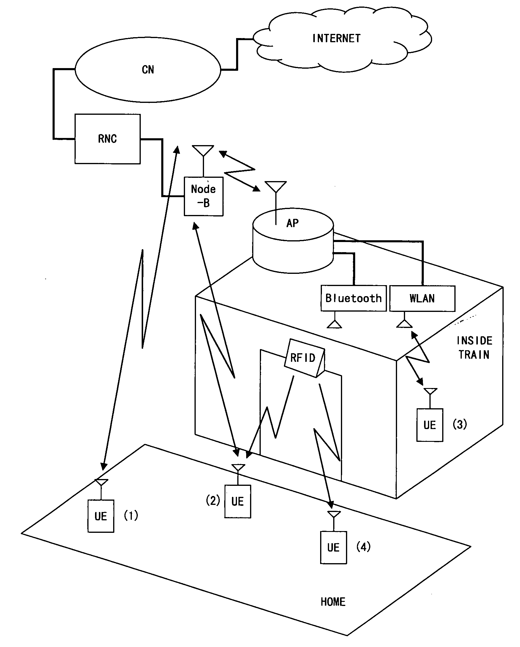
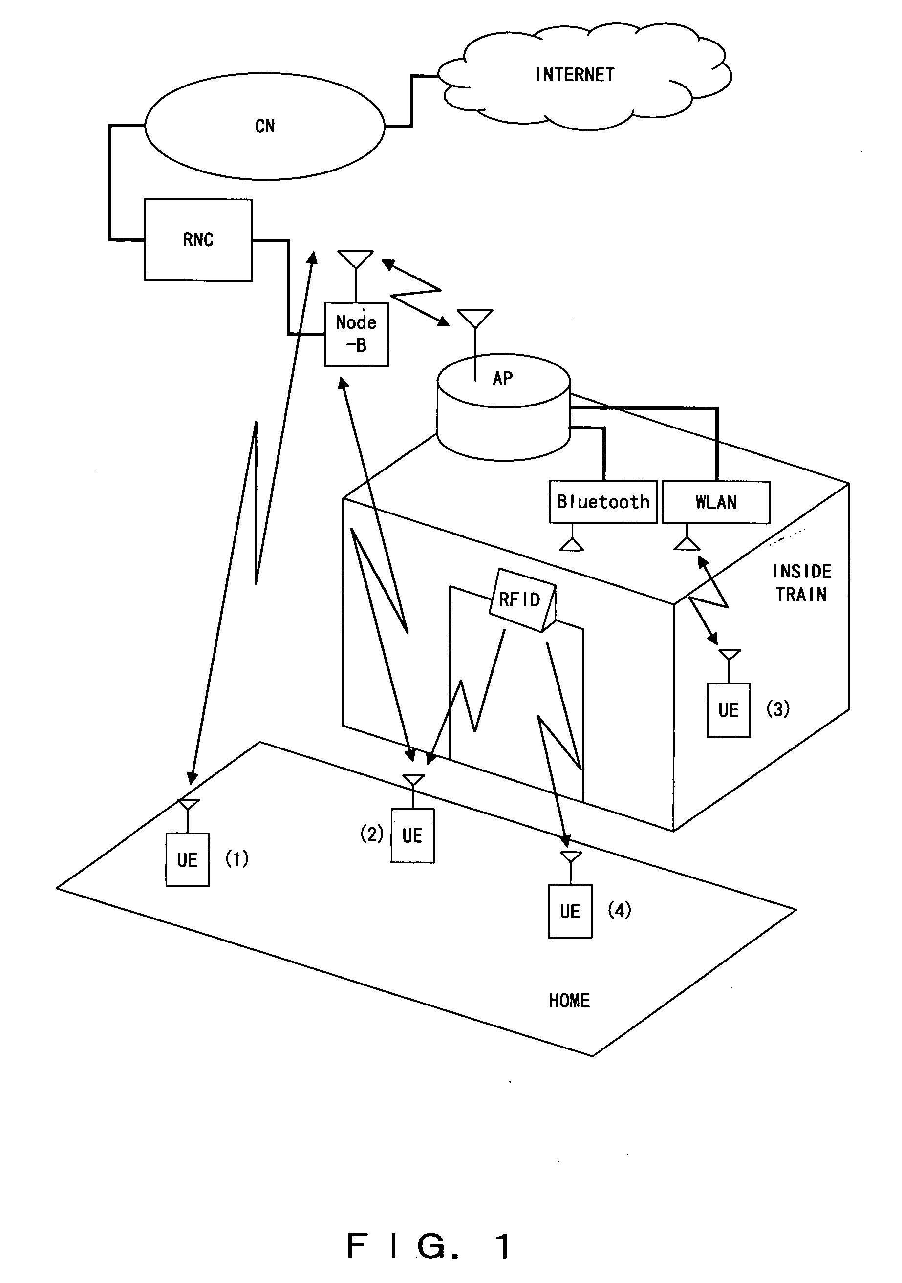
[0047]FIG. 1 is a diagram describing a configuration for a telecom system according to a preferred embodiment of the present invention.

[0048]The system, according to a preferred embodiment of the present invention, comprises: mobile devices ...


PUM


Abstract

A mobile terminal UE accesses a CN and utilizes the Internet via a base station Node-B. When riding an electric train, the mobile terminal UE receives a disembarkation notification and an embarkation notification from a RFID tag writer equipped on a train, and notifies the base station Node-B that the terminal is on-board the train. While on-board the train, the terminal accesses an in-vehicle AP by employing a WLAN, Bluetooth, or similar system, and the in-vehicle AP communicates with the base station Node-B. This configuration enables the in-vehicle AP to handle all of the mobile devices existing on a train in a centralized manner, thereby eliminating the need for each of the mobile devices to individually access the base station Node-B.

Description

CROSS-REFERENCE TO RELATED APPLICATIONS[0001]This application is a continuation application of an international application No. PCT / JP2005 / 004926.BACKGROUND OF THE INVENTION[0002]1. Field of the Invention[0003]The present invention relates to a telecommunication system for telecommunicating via an apparatus that handles radio waves, such as a mobile telecommunications apparatus, that goes into and comes out of a means for transporting a passenger and cargo (herein after referred to as a “vehicle”), wherein the vehicle may be a bus, airplane, vessel, electric train, or other transportation means.[0004]2. Description of the Related Arts[0005]In the current location registration system, congestion of a radio environment occurs when a plurality of mobile devices, that are traveling in a vehicle, carry out individual location registrations for a network (e.g., congestion occurs when an electric train or bus moves across location registration areas.)[0006]In order to avoid this congestion...

Claims


Application Information

Patent Timeline
Patent Type & Authority Applications(United States)
IPC IPC(8): H04Q7/38H04W60/00H04W60/04H04W76/04H04W84/00
CPCH04B7/18506H04W84/005H04W60/04H04W60/00
Inventor NITTA, DAISUKEKUMAGAI, TOMONORIKOBAYASHI, KAZUNARI
Owner FUJITSU LTD
Learn More