Cellular system

a cellular system and system technology, applied in the field of cellular systems, can solve the problems of radio signals, radio signals are likely to be affected, and the quality of receipts is likely to be deteriorated, so as to achieve the effect of minimizing influen

Inactive Publication Date: 2005-01-11
NEC CORP
View PDF14 Cites 20 Cited by
  • Summary
  • Abstract
  • Description
  • Claims
  • Application Information

AI Technical Summary

Benefits of technology

In view of the above-mentioned problems in the conventional cellular system or method of controlling power at which a radio signal is transmitted, it is an object of the present invention to provide a cellular system which mi

Problems solved by technology

If those radio waves much interfere with each other, receipt quality in a desired radio wave would be deteriorated, resulting in disconnection in communication lines.
The soft handover technique ensures a mobile station to have enhanced receipt quality by virtue of diversity effect brought by transmission from a plurality of base stations even in the vicinity of a boundary among cells where transmission lose is usually high, and hence, receipt quality is likely to be deteriorated.
However, downward line is accompanied with a problem that since a plurality of base stations transmit radio signals during soft hand-over, radio signals would interference with one another with the result of reduction in line capacity.
However, the above-mentioned conventional method of controlling power at which a radio signal is transmitted is accompanied with a problem that a base station might wrongly receive a designation signal by which the base station is designated as a transmission base statio

Method used


Image

  • Cellular system
  • Cellular system
  • Cellular system

Examples


first embodiment

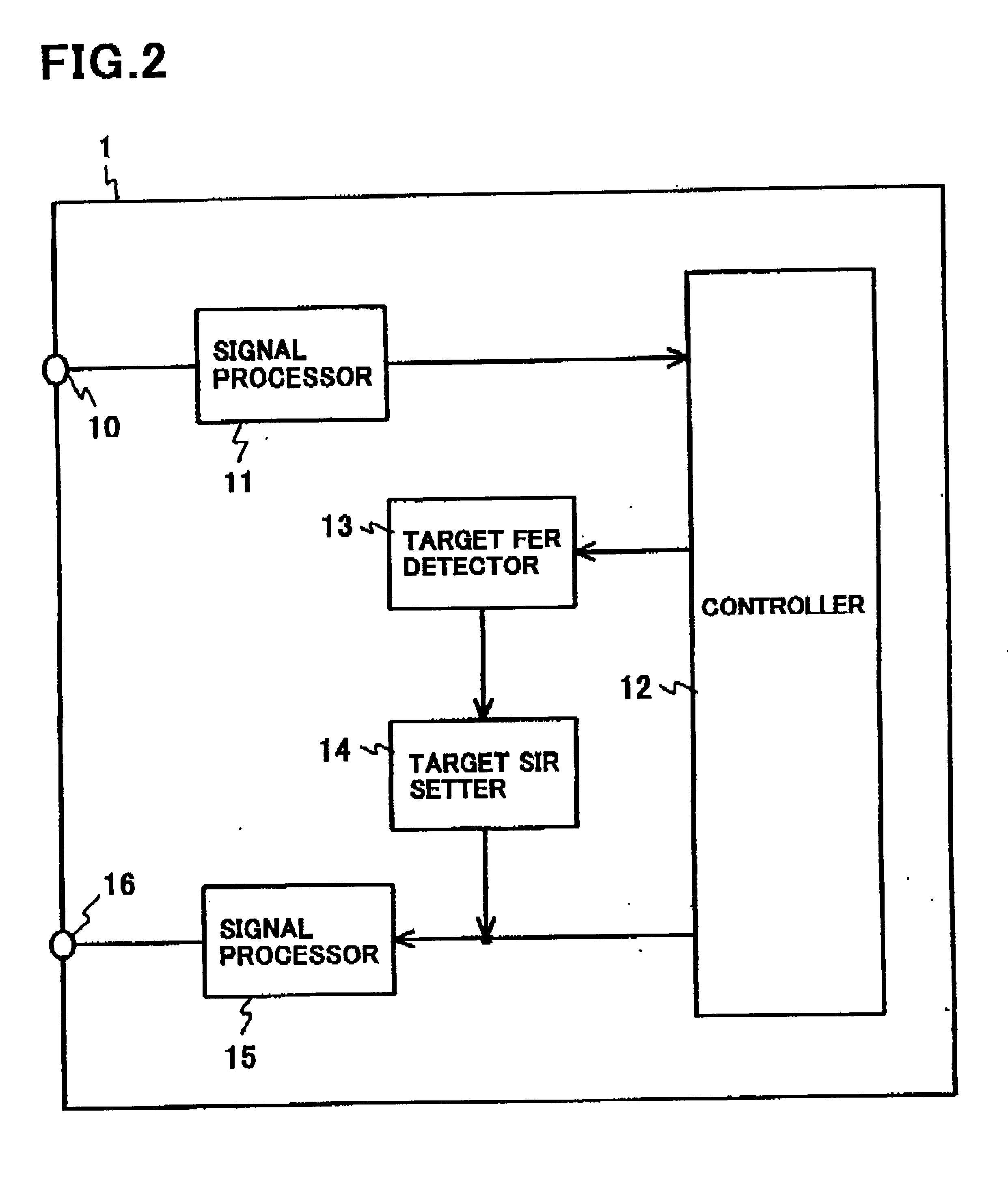
FIG. 2 is a block diagram of the base station controller 1 in accordance with the

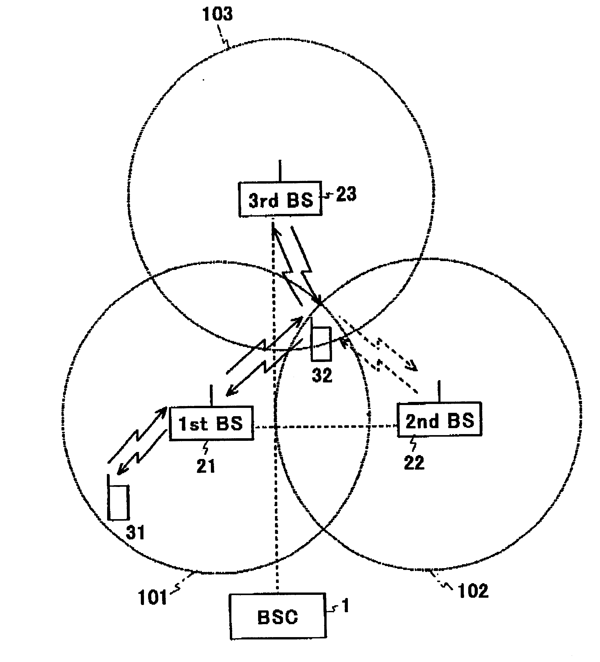
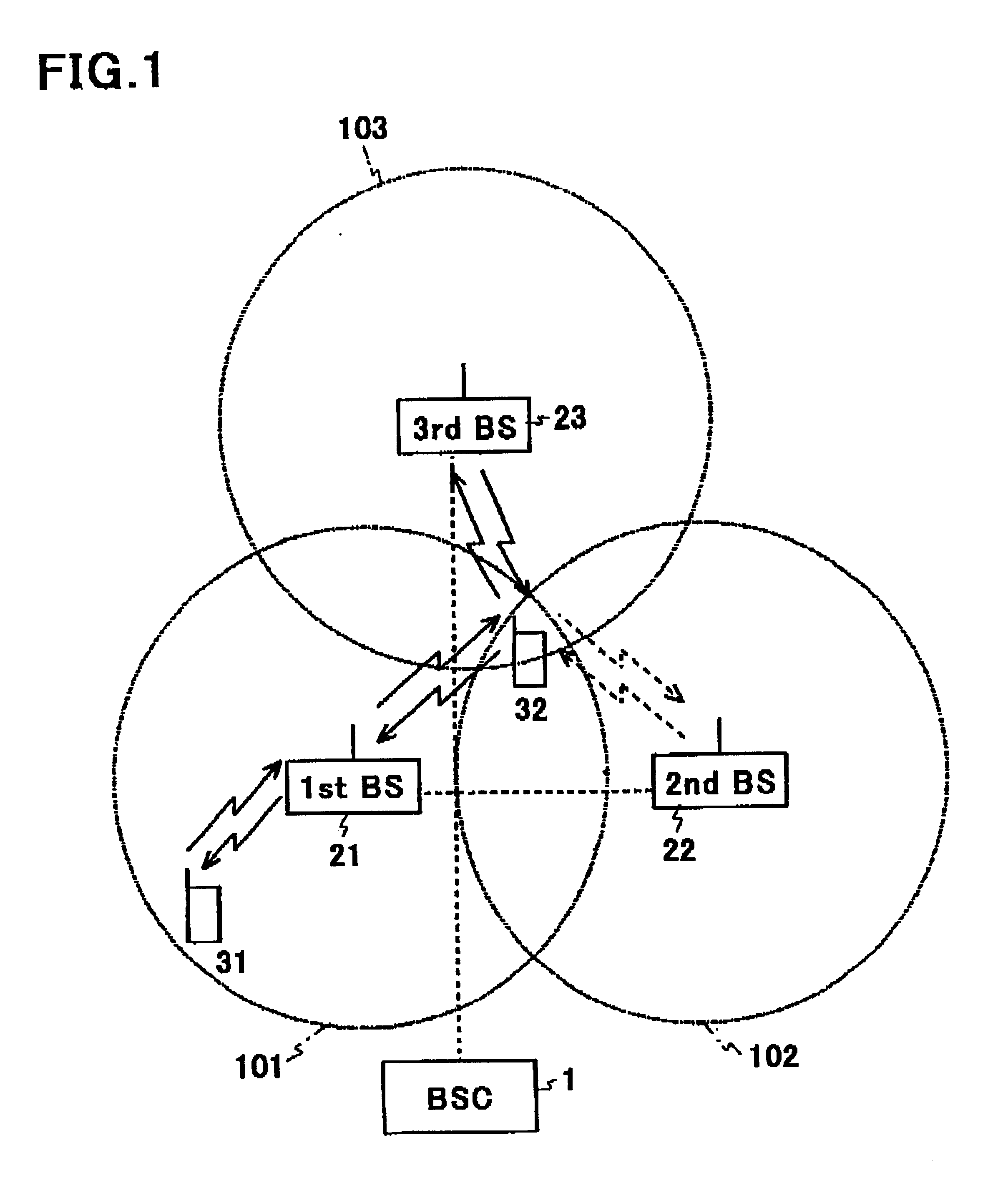
With reference to FIG. 2, the base station controller 1 is comprised of an input terminal 10 through which signals transmitted from the first to third base stations 21 to 23 are received, a signal processor 11 which processes received signals, a controller 12 which controls signal transmission to and signal receipt from the first to third base stations 21 to 23, a target FER detector 13 which detects a target frame error rate (FER) in downward line, transmitted from a host network, a target SIR setter 14 which determines a target signal interference ratio (SIR) in upward line to the fist to third base stations 21 to 23, in accordance with the detected target FER, a signal processor 15 which processes signals to be transmitted from the base station controller 1, and an output terminal 16 through which signals are transmitted to the first to third base stations 21 to 23.

The target SIR setter 14 determines...

second embodiment

FIG. 4 is a block diagram of a base station controller 4 in accordance with the

With reference to FIG. 4, the base station controller 4 in accordance with the second embodiment is designed to have the same structure as the structure of base station controller 1 illustrated in FIG. 2 except that the base station controller 4 includes an offset power controller 41 in place of the target SIR setter 14 illustrated in FIG. 2. Parts or elements that correspond to those of the base station controller 1 illustrated in FIG. 2 have been provided with the same reference numerals, and operate in the same manner as corresponding parts or elements in the base station controller 1.

The offset power controller 41 determines offset power of an individual control signal to an individual information signal in upward line in accordance with a target FER, and transmits the thus determined offset power to the second mobile station 32 in downward line through the first and third base stations 21 and 23.

FIG....

third embodiment

FIG. 6 is a block diagram of a base station controller 5 in accordance with the

With reference to FIG. 6, the base station controller 5 in accordance with the third embodiment is designed to have the same structure as the structure of base station controller 1 illustrated in FIG. 2 except that the base station controller 5 includes a designation signal length controller 51 in place of the target SIR setter 14 illustrated in FIG. 2. Parts or elements that correspond to those of the base station controller 1 illustrated in FIG. 2 have been provided with the same reference numerals, and operate in the same manner as corresponding parts or elements in the base station controller 1.

The designation signal length controller 51 determines a signal length of a designation signal to be transmitted in upward line together with an individual control signal, in accordance with a target FER, and transmits the thus determined designation signal length to the second mobile station 32 in downward lin...


PUM


Abstract

A cellular system includes a mobile station and base stations, wherein the mobile station establishes a communication line with N first base stations wherein N is an integer (1≦N), measures receipt quality in pilot signals transmitted from the N first base stations, determines M second base stations to make communication therethrough among the N first base stations, based on measurement results of the receipt quality, wherein M is an integer (1≦M≦N), and transmits an designation signal to the M second base stations through upward line to designate the M second base stations as a base station through which the mobile station makes communication, and each of the base stations makes communication with the mobile station, if designated by the designation signal, and does not make communication with the mobile station, if not designated. The cellular system further includes a first apparatus for varying a signal-receipt error rate in the designation signal to be transmitted through upward line in accordance with a target signal-receipt error rate in downward line.

Description

BACKGROUND OF THE INVENTION1. Field of the InventionThe invention relates to a cellular system and a method of controlling power at which a signal is transmitted in a cellular system, and more particularly to a cellular system and a method for controlling communication at a base station during hand-over.2. Description of the Related ArtIn a cellular system operating in direct sequence-code division multiple access (DS-CDMA), since a common frequency band is assigned to a plurality of channels, radio waves for the plurality of channels and radio waves for other channels would interfere with each other. If those radio waves much interfere with each other, receipt quality in a desired radio wave would be deteriorated, resulting in disconnection in communication lines. Hence, the number of lines through which communication can be made with desired receipt quality being maintained, that is, line capacity is dependent on how much radio waves interfere with other.A signal transmitted from ...

Claims


Application Information

Patent Timeline
IPC IPC(8): H04B7/005H04Q7/38H04B7/26H04W36/08H04W36/18H04W36/28H04W36/38H04W52/40H04W88/12H04W92/12
CPCH04W36/18H04W52/40H04W36/30H04W92/12H04W88/12H04B7/26
Inventor TAKANO, NAHOKOHAMABE, KOJIRO
Owner NEC CORP
Why Eureka
Try Eureka