Method and apparatus for high resolution tracking via mono-pulse beam-forming in a communication system

a communication system and beamforming technology, applied in diversity/multi-antenna systems, direction finders using radio waves, instruments, etc., can solve the problems of reducing the capacity of the network, switching beam systems do not take advantage of the maximum gain offered, and the prognosis of data rates and aggregate capacity cannot be supported in a small region, so as to improve the range and capacity of mobile or fixed wireless communication base stations.

Inactive Publication Date: 2005-08-16
TEXAS INSTR INC
View PDF9 Cites 19 Cited by
  • Summary
  • Abstract
  • Description
  • Claims
  • Application Information

AI Technical Summary

Benefits of technology

[0012]In one embodiment of the invention the capacity and range of mobile or fixed wireless communication base stations are improved by implementing a single or multiple antenn...

Problems solved by technology

As a result, the promised data rates and aggregate capacity can only be supported in a small region close to the base station.
These switched-beam systems do not take advantage of the maximum gain offered by the full aperture.
Unfortunately, this method requires handoff between the sub-sectors just as with a standard 3-sector system.
These handovers require valuable resources and ultimately reduce the capacity of the network.
These methods vary in complexity.
It is considered sub-optimal because it does not attempt to place nulls on significant interference and thus does not maximizing SINR.
Furthermore, ubiquitous multi-path propagation with uncorrelated fading would require at least two paths to be resolved requiring means for several channels.
Although this technique is considered optimum combining because it maximizes SINR it has the disadvantage that its solution does not necessarily place the peak of an antenna beam on the desired signal path.
The effect of this is the degradation in sensitivity of the system to the thermal noise thus reducing the rang...

Method used


Image

  • Method and apparatus for high resolution tracking via mono-pulse beam-forming in a communication system
  • Method and apparatus for high resolution tracking via mono-pulse beam-forming in a communication system
  • Method and apparatus for high resolution tracking via mono-pulse beam-forming in a communication system

Examples


Embodiment Construction

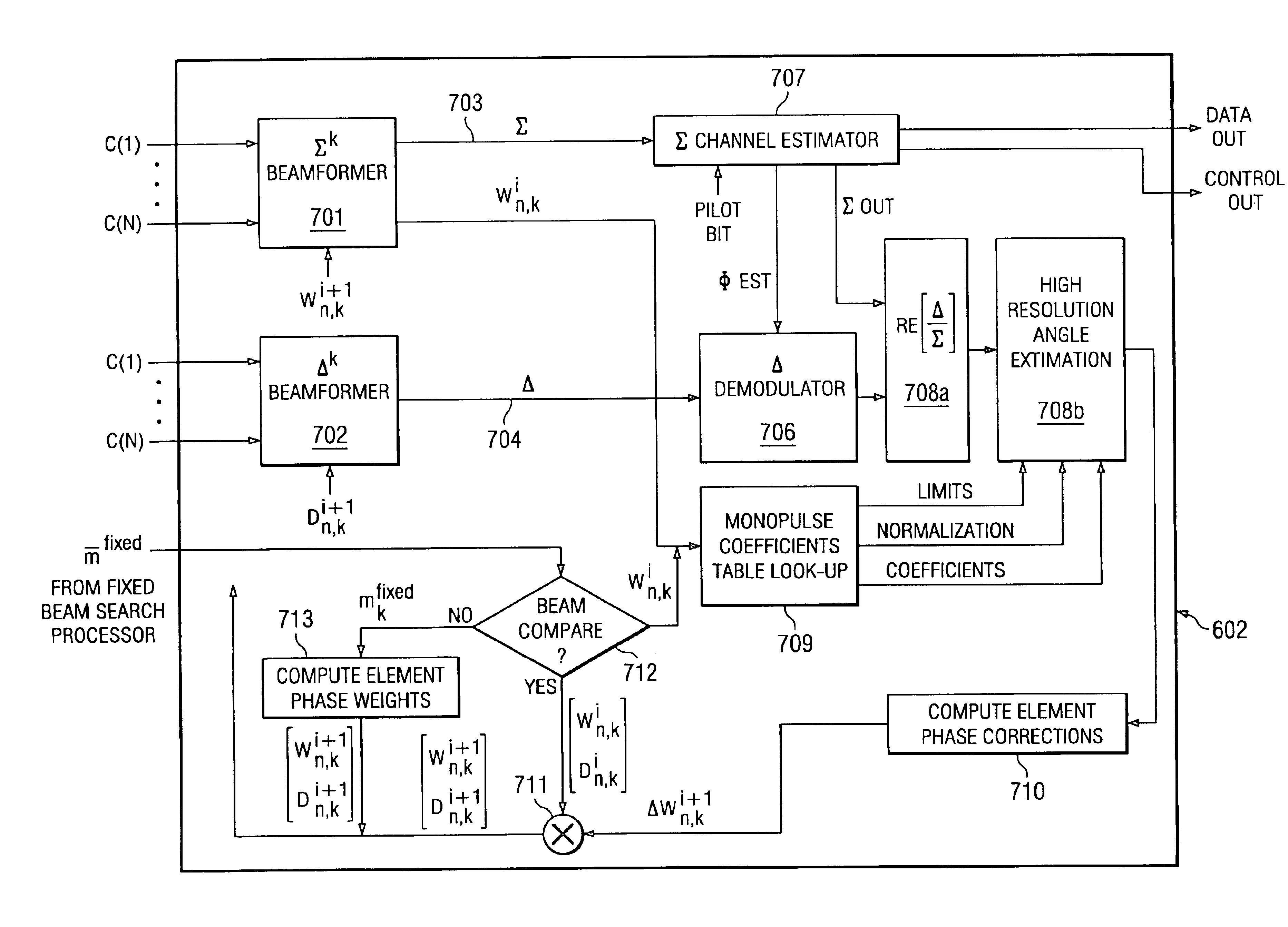
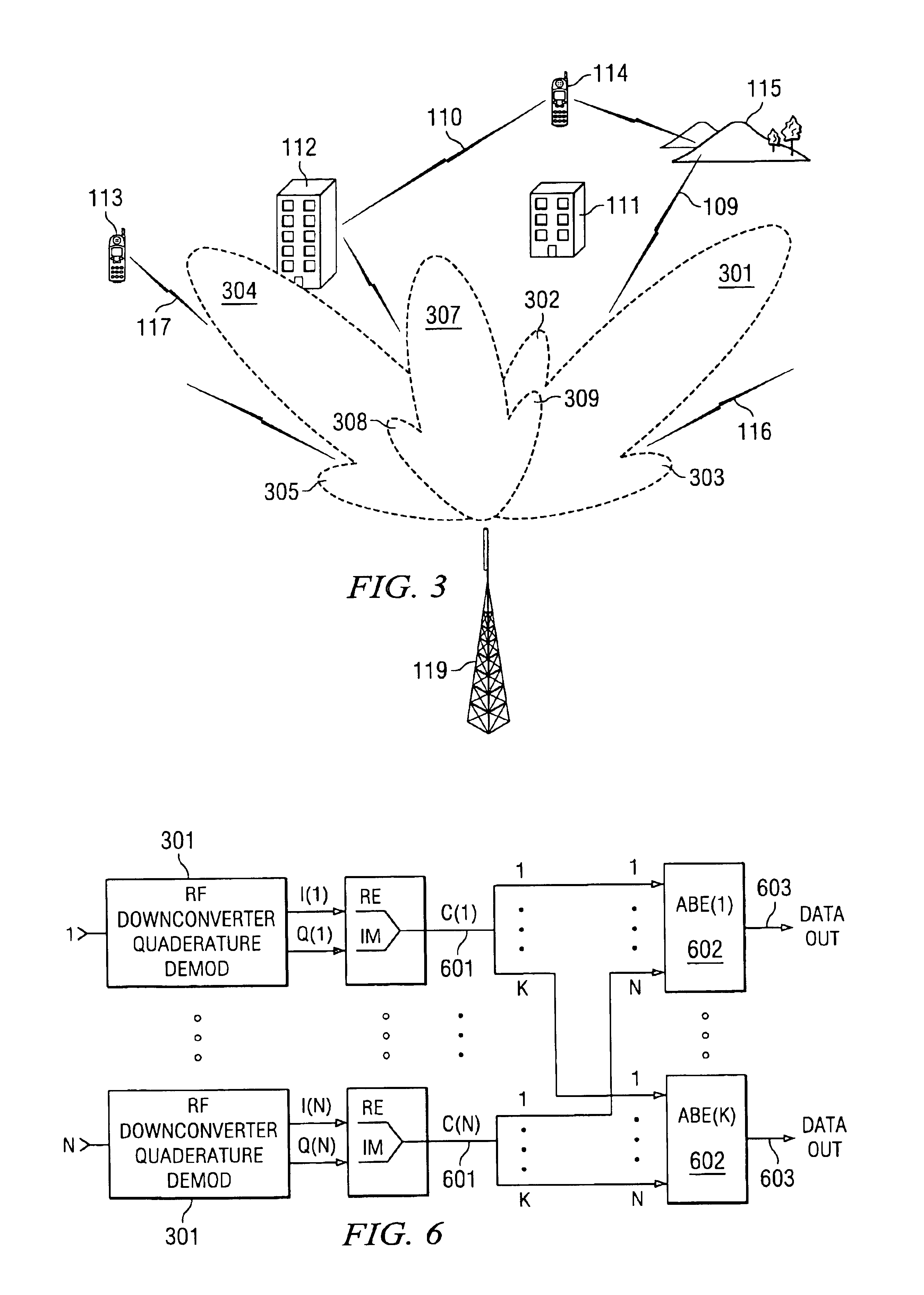
[0022]Adaptive beam-forming can be implemented digitally in the base-band. Therefore, some means of down-converting an RF signal to base-band as well as a scheme for calibration is assumed. The algorithm can be divided into two steps: 1) a low resolution search performed by the fixed beam searcher, 2) high resolution tracking which utilizes standard mono-pulse techniques. Alternatively, if the approximate location of the mobile or fixed wireless user is known or is determined by other means the low resolution track can be circumvented with high resolution mono-pulse tracking only. The simplicity of this direction-of-arrival estimation calculation will enable real time tracking of a mobile station within the sector area serviced by the antenna.

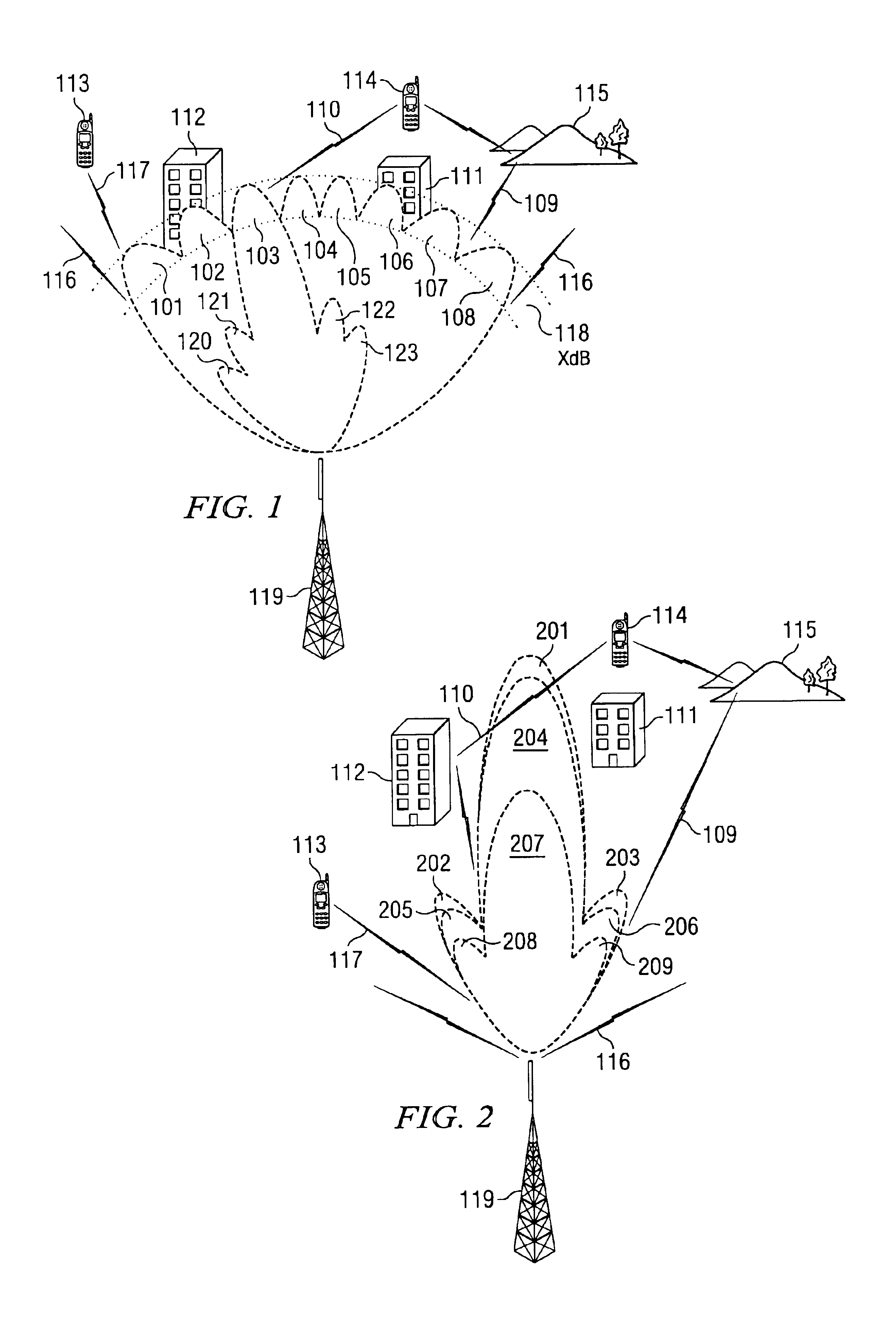
[0023]The low resolution search is performed by comparing the signals in each of the beams that sub-divide the sector, (eg. 101-108). The signals may be line of sight (LOS) or a time delayed non-LOS multi-path. The base station equipment will d...


PUM


Abstract

Method and apparatus for high resolution tracking via mono-pulse beam-forming in a communication system in which the capacity and range of mobile or fixed wireless communication base stations are improved by implementing a single or multiple antenna beam per signal path. Adaptive beam-forming based on up-link direction-of arrival estimation can be performed without using the above-mentioned computationally intensive techniques.

Description

[0001]This application claims priority under 35 USC §119(e)(1) of provisional application number 60 / 331,423, filed Nov. 15, 2001.BACKGROUND OF THE INVENTION[0002]The invention relates to base station equipment for receiving and transmitting one or more signals from one or more users, in which the signals may arrive at the equipment along a multiplicity of paths, from possibly different directions, and with possibly different delays.[0003]A major concern for providers of wireless communications services is system coverage and capacity. Future systems promise data rates and an aggregate capacity significantly higher than current systems. However, with conventional base stations, the maximum link closure range will be decreased substantially for users operating at higher data rates. As a result, the promised data rates and aggregate capacity can only be supported in a small region close to the base station.[0004]Smart antenna systems have been discussed in the literature as a means of ...

Claims


Application Information

Patent Timeline
IPC IPC(8): G01S3/32G01S3/14H01Q25/02H01Q25/00H04B7/04H04B7/08H04B7/06
CPCG01S3/32H01Q25/02H04B7/0617H04B7/086
Inventor BROTHERS, JR., LOUIS R.CANGEME, JOHNFLAIG, ALEXANDERMACMULLEN, SAMUEL J.POOR, H. VINCENTRAO, TANDHONI S.SCHWARTZ, STUART C.UPADHYAY, TRIVENI N.
Owner TEXAS INSTR INC
Why Eureka
Try Eureka