Implant, a mandrel, and a method of forming an implant

a coil and implant technology, applied in the field of implantable coils, can solve the problems of insufficient stability of the secondary structure of the resulting coils to retain their conformity with the vascular site, and ineffective embolization of the vascular site, and achieve the effect of effective embolization

Active Publication Date: 2008-09-18
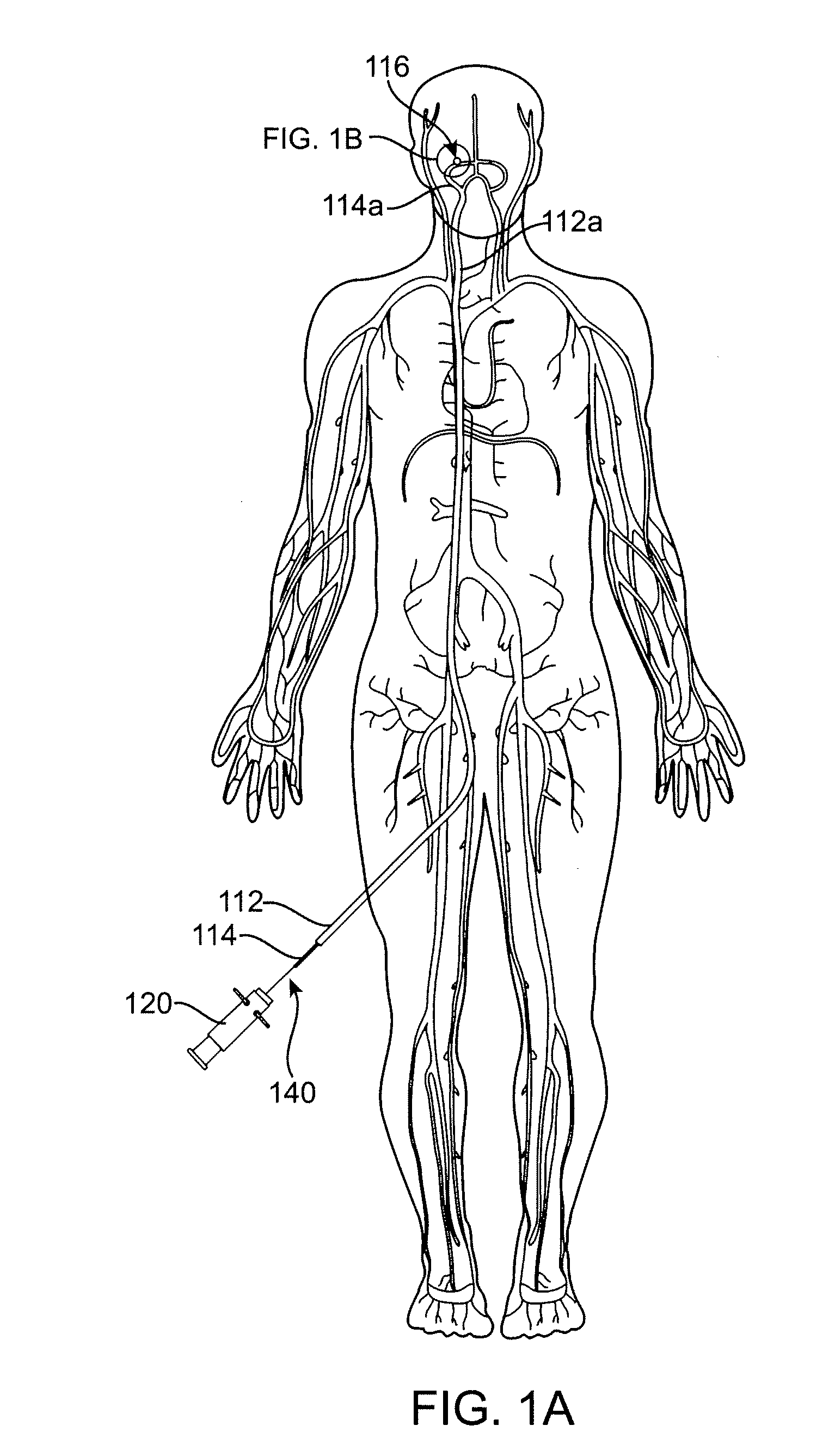
TYCO HEALTHCARE GRP LP
View PDF101 Cites 86 Cited by
  • Summary
  • Abstract
  • Description
  • Claims
  • Application Information

AI Technical Summary

Benefits of technology

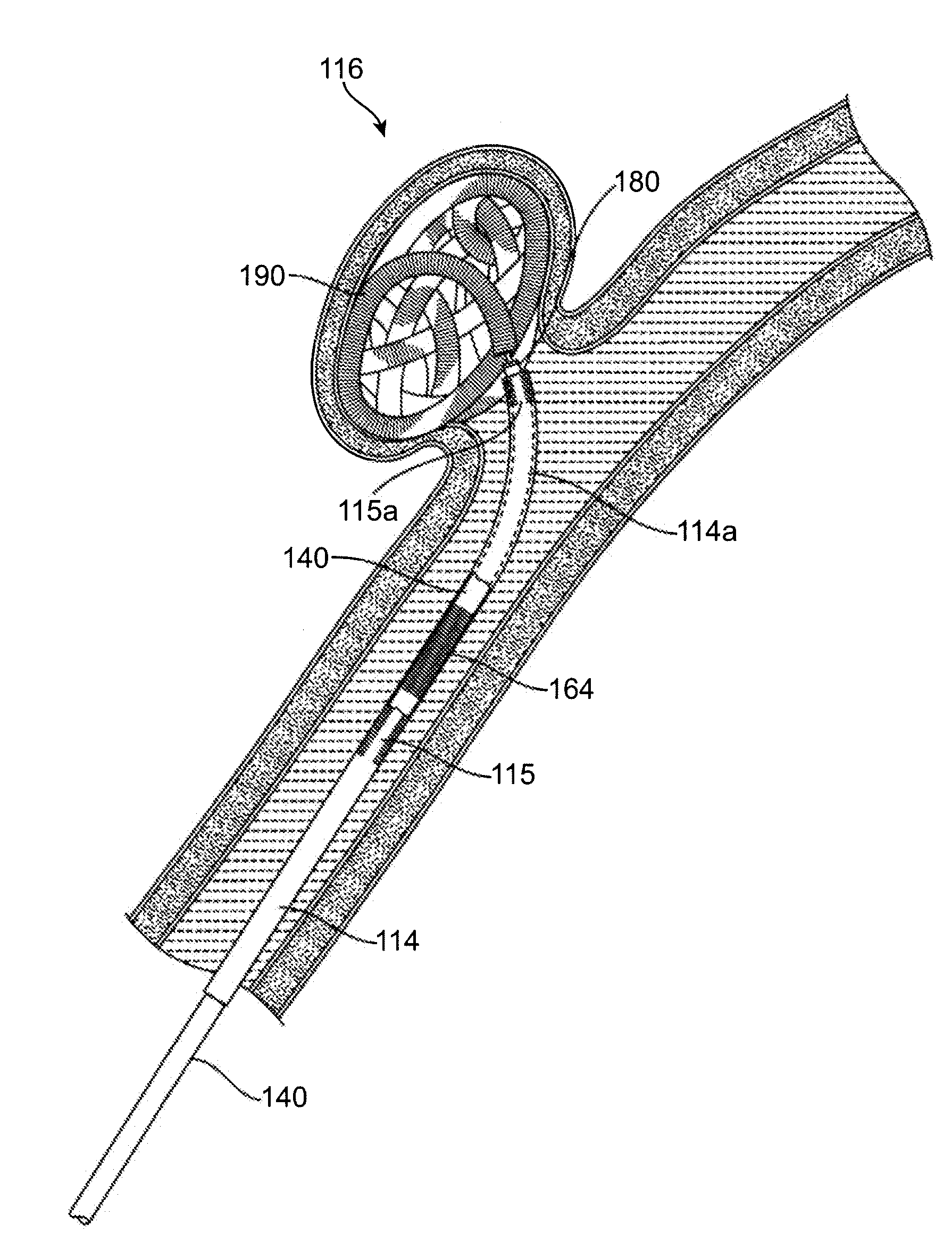
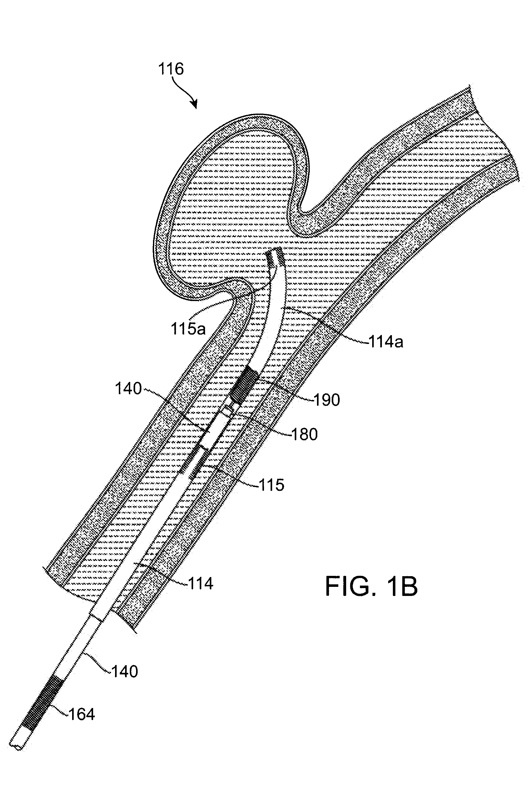
[0006]The invention, in one embodiment, is directed to an implant comprising a 3-dimensional coil designed to optimize packing into a vascular site, such as an aneurysm. It is contemplated that the implant of the invention, due to its

Problems solved by technology

However, the in vivo formed coils of the prior art invariably failed to provide shapes which comport to the vascular site and this results in the ineffective embolization of the vascular site.
Even when the

Method used


Image

  • Implant, a mandrel, and a method of forming an implant
  • Implant, a mandrel, and a method of forming an implant
  • Implant, a mandrel, and a method of forming an implant

Examples


example 1

Method of Making the Implant

[0053]An implant of the invention may be made by the following procedure.[0054]1. Under microscope insert the distal end of the wire or coil into the starter tube.[0055]2. Wind coil around mandrel as described above and in FIG. 8.[0056]3. Heat set the coil and the mandrel. The temperature is from about 550° C. to about 650° C.

example 2

Comparison of Other Three-Dimensional Shapes

[0057]The coil of the invention was tested and compared with coils having a cubic three-dimensional (3-D) shape and a spherical (or spheroidal) 3-D shape. The clinicians assessed the ability of the coil to compact into the vascular site and the ability of the coil to conform to the shape of the vascular site.

Protocol

[0058]The coils of the invention were obtained according to Example 1. The mobius loop coils of the invention were made on a 10 millimeter (mm) sphere with four 8 mm markers. The coils having a cubic 3-D were made by winding wire around a mandrel having six markers (rather than the four to obtain the coils of the invention), one on each face of the cube. One marker was 5 mm and the other five markers were 8 mm. The sphere was 10 mm. The spherical coil were obtained by winding wire around a base mandrel with eight markers. The sphere was again 10 mm and the markers were about 5 mm.

[0059]Once the coils were wound according to the...


PUM


Abstract

This invention is directed to an implant having a coil for embolizing a vascular site, such as aneurysm. The coil has a specific three-dimensional shape that is achieved by winding the coil around a mandrel in a specific pattern and then heat setting the coil and the mandrel, another aspect of the invention. The three-dimensional shape resembles unclosed mobius loops. Also provided are methods of making the coil and methods of embolizing vascular site.

Description

RELATED APPLICATIONS[0001]This application claims the benefit under 35 U.S.C. § 119(e) of provisional application Ser. Nos. 60 / 894,589 filed Mar. 13, 2007, 60 / 894,865 and 60 / 894,858 both filed on Mar. 14, 2007, all of which are hereby incorporated by reference in their entirety.FIELD OF THE INVENTION[0002]This invention relates to the forming of implantable coils and to coils formed by such methods as well as to a mandrel used to form the shape of a coil implant, a method of forming a coil implant, and a coil implant formed by such method or with such mandrel.BACKGROUND OF THE INVENTION[0003]Implants are delivered to a vascular site, such as an aneurysm, of a patient via a microcatheter to occlude or embolize the vascular site. Typically, the implant is engaged at the distal end of either the delivery microcatheter or the guidewire contained within the microcatheter and controllably released therefrom into the vascular site to be treated. The clinician delivering the implant must na...

Claims


Application Information

Patent Timeline
IPC IPC(8): A61F2/01A61B17/12B65H16/02
CPCA61B17/12022A61B17/12113A61B17/12145A61B2017/00867A61B2017/00526A61B2017/00862A61B17/12154A61F2/06A61F2/07A61L27/04
Inventor STRAUSS, BRIAN MICHAELHEWITT, TODD JEFFREYCARRILLO, RAMON TORRESVU, KHOA DANGPATTERSON, WILLIAM ROBERTWILBUR, LARRYKLOTZ, JUSTINBRENNAN, SCOTT WILLIAMDIVINO, VINCE
Owner TYCO HEALTHCARE GRP LP
Why Eureka
Try Eureka