Vascular embolization with an expansible implant

a vascular embolization and expansible technology, applied in the field of methods and devices, can solve the problems of balloon rupture during inflation, difficult to retrieve or move after solidifying fluid sets, and difficult visualization, and achieve the effects of effective vascular embolization implants, excellent location control, and reduced risk of vascular rupture, tissue damage, or migration

Inactive Publication Date: 2006-04-18
MICROVENTION INC
View PDF70 Cites 173 Cited by
  • Summary
  • Abstract
  • Description
  • Claims
  • Application Information

AI Technical Summary

Benefits of technology

[0022]The present invention provides a number of significant advantages. Specifically, the present invention provides an effective vascular embolization implant that can be deployed within a vascular site with excellent locational control, and with a lower risk of vascular rupture, tissue damage, or migration than with prior art implant devices. Furthermore, the implant device, by being modelled on the actual vascular site in which it is to be implanted, effects a conformal fit within the site that promotes effective embolization, an

Problems solved by technology

While the balloon-type embolization device can provide an effective occlusion of many types of aneurysms, it is difficult to retrieve or move after the solidifying fluid sets, and it is difficult to visualize unless it is filled with a contrast material.
Furthermore, there are risks of balloon rupture during inflation and of premature detachment of the balloon from the catheter.
The direct injection of liquid polymer embolic agents has proven difficult in practice.
For example, migration of the polymeric material from the aneurysm and into the adjacent blood vessel has presented a problem.
In addition, visualization of the embolization material requires that a contrasting agent be mixed with it, and selecting embolization materials and contrasting agents that are mutually compatible may result in performance compromises that are less than optimal.
Furthermore, precise control of the deployment of the polymeric embolization material is difficult, leading to the risk of improper placement and/or premature solidification of the material.
Moreover, once the embolization material is deployed and solidified, it is difficult to move or retrieve.
Microcoils have been less successful in the treatment of larger aneurysms, especially those with rel

Method used


Image

  • Vascular embolization with an expansible implant
  • Vascular embolization with an expansible implant
  • Vascular embolization with an expansible implant

Examples


Embodiment Construction

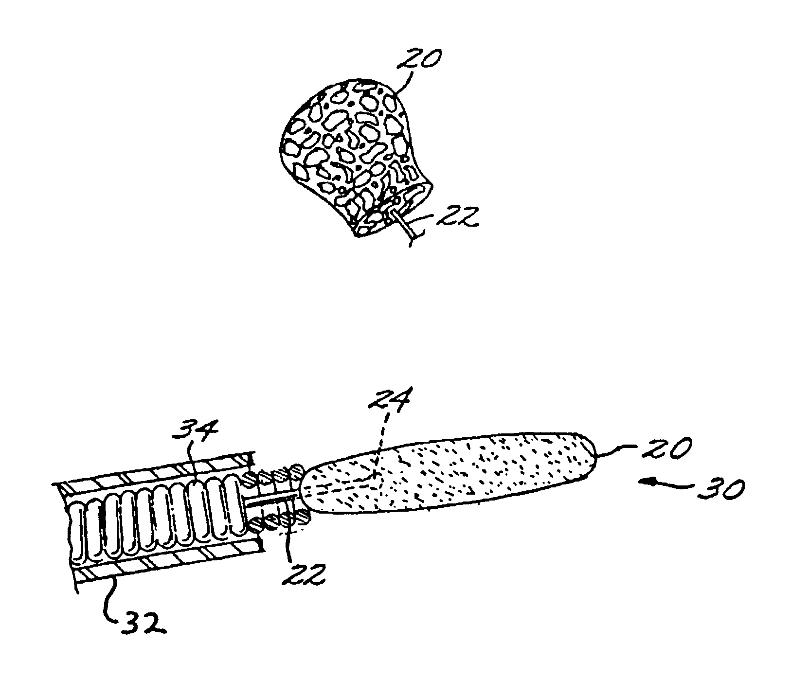
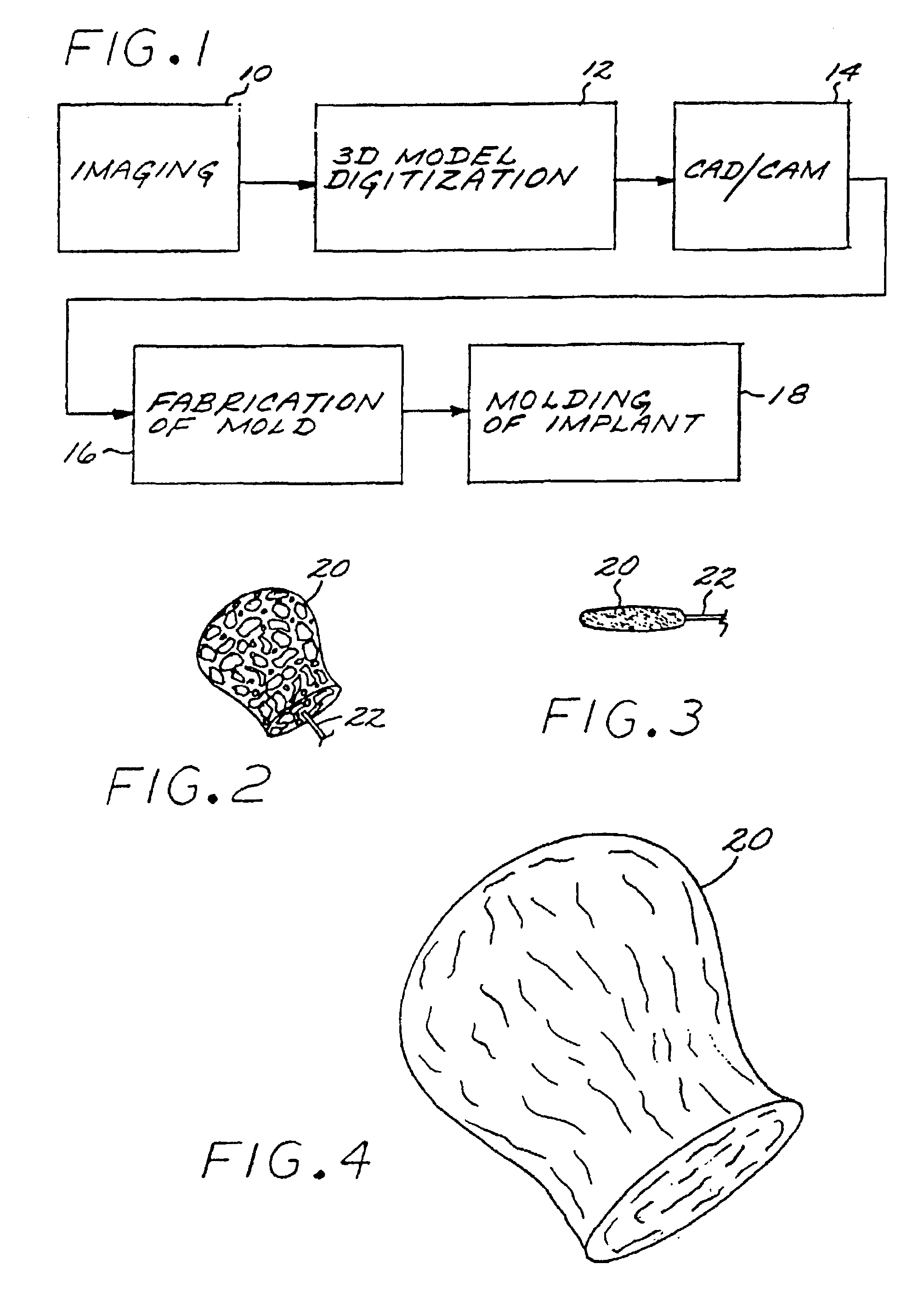
[0029]The Method of Manufacturing a Vascular Implant. A first aspect of the present invention is a method of manufacturing a vascular implant device. The steps of a preferred embodiment of the manufacturing method are shown as a sequence of descriptive boxes in the flow chart of FIG. 1.

[0030]The first step, shown in box 10 of FIG. 1, is the step of creating an image of a vascular site, such as an aneurysm, in which an embolizing implant is to be installed. This imaging step is performed by scanning the site using any of several conventional imaging techniques, such as computer tomography, magnetic resonance imaging (MRI), magnetic resonance angiography (MRA), or ultrasound.

[0031]The result of the imaging step is a digitized scan data set that is stored in a computer memory, from which the data set is retrieved for operation of the next step: computerized reconstruction of a three-dimensional digitized virtual model of the vascular site (box 12 of FIG. 1). This step of creating a thr...


PUM

PropertyMeasurementUnit
Pressureaaaaaaaaaa
Flexibilityaaaaaaaaaa

Abstract

A vascular implant formed of a compressible foam material has a compressed configuration from which it is expansible into a configuration substantially conforming to the shape and size of a vascular site to be embolized. Preferably, the implant is formed of a hydrophilic, macroporous foam material, having an initial configuration of a scaled-down model of the vascular site, from which it is compressible into the compressed configuration. The implant is made by scanning the vascular site to create a digitized scan data set; using the scan data set to create a three-dimensional digitized virtual model of the vascular site; using the virtual model to create a scaled-down physical mold of the vascular site; and using the mold to create a vascular implant in the form of a scaled-down model of the vascular site. To embolize a vascular site, the implant is compressed and passed through a microcatheter, the distal end of which has been passed into a vascular site. Upon entering the vascular site, the implant expands in situ substantially to fill the vascular site. A retention element is contained within the microcatheter and has a distal end detachably connected to the implant. A flexible, tubular deployment element is used to pass the implant and the retention element through the microcatheter, and then to separate the implant from the retention element when the implant has been passed out of the microcatheter and into the vascular site.

Description

CROSS REFERENCE TO RELATED APPLICATION[0001]This application is a Division of application Ser. No. 09 / 730,071; filed Dec. 5, 2000 now U.S. Pat. No. 6,500,190, which is a Continuation of application Ser. No. 09 / 110,816; filed Jul. 6, 1998 now U.S. Pat. No. 6,165,193.FEDERALLY SPONSORED RESEARCH OR DEVELOPMENT[0002]Not applicableBACKGROUND OF THE INVENTION[0003]The present invention relates to the field of methods and devices for the embolization of vascular aneurysms and similar vascular abnormalities. More specifically, the present invention relates to (a) an expansible vascular implant that is inserted into a vascular site such as an aneurysm to create an embolism therein; (b) a method of making the expansible implant; and (c) a method and an apparatus for embolizing a vascular site using the implant.[0004]The embolization of blood vessels is desired in a number of clinical situations. For example, vascular embolization has been used to control vascular bleeding, to occlude the blo...

Claims


Application Information

Patent Timeline
IPC IPC(8): A61B19/00A61B17/12A61F2/02A61L31/14A61L31/18
CPCA61B17/12022A61B17/12186A61B17/1219A61L31/145A61L31/146A61L31/18A61B17/12113A61F2/06A61B19/50A61B2017/00526A61B2017/1205A61L2430/36Y10S623/901Y10S623/903Y10T29/49A61B34/10B33Y80/00B33Y50/00
Inventor GREENE, JR., GEORGE R.ROSENBLUTH, ROBERT F.COX
Owner MICROVENTION INC
Why Eureka
Try Eureka