
Flash memory device and memory system

a flash memory and memory technology, applied in the field of electronic memories, can solve the problems of limiting the operating speed, affecting the performance of flash memory, and wasting time on flash memory operation,

Active Publication Date: 2008-09-18
SAMSUNG ELECTRONICS CO LTD
View PDF3 Cites 149 Cited by
  • Summary
  • Abstract
  • Description
  • Claims
  • Application Information

AI Technical Summary

Benefits of technology

[0009]One aspect of the present disclosure includes a memory system. The memory system comprises a flash memory, a processing unit, and a flash controller including address and control registers, the address and control registers being configured to receive information from the processing unit, wherein the flash controller is configured to control a copy-back program operation of the flash memory in hardware based on information stored in the address and control registers.
[0010]

Problems solved by technology

While the storage capacities of flash memories are being increased, the performance of flash memories may be limited by a number of factors.
For example, certain operations need to be performed in a flash memory device that may limit the operating speed, i.e., the speed at which data may be written to and read from the flash memory device.
However, the time taken to perform these operations using firmware may be more than the time taken if these operations were to be performed in hardware.
Furthermore, the time needed to perform these operations may limit the overall operating speed of the memory device.
This problem may be exacerbated as the amount of data stored in the memory device increases.

Method used


Image

  • Flash memory device and memory system
  • Flash memory device and memory system
  • Flash memory device and memory system

Examples


Embodiment Construction

[0023]The present disclosure will now be described more fully hereinafter with reference to the accompanying drawings, in which exemplary embodiments of the disclosure are shown. This invention, however, may be embodied in many different forms and should not be construed as limited to the embodiments set forth herein. Rather, these embodiments are provided so that this disclosure will be thorough and complete, and will fully convey the scope of the invention to those skilled in the art. In the drawings, like numbers refer to like elements throughout.

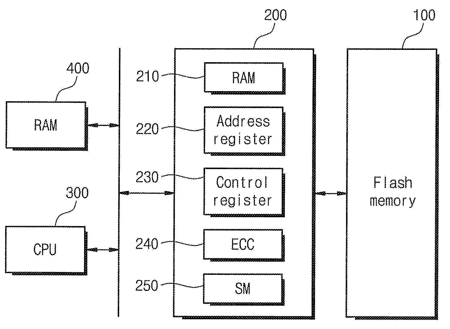
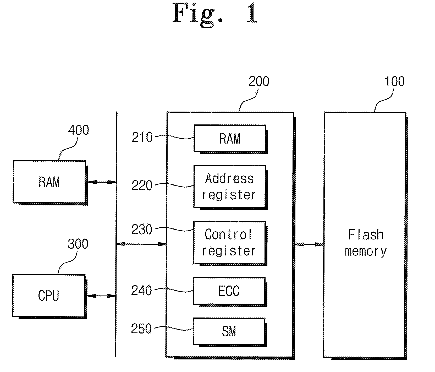
[0024]FIG. 1 is a block diagram showing a flash memory-based memory system according to an exemplary disclosed embodiment. Referring to FIG. 1, an exemplary flash memory system includes a flash memory 100, a flash controller200, a central processing unit (CPU) 300, and RAM 400, all of which are electrically connected to a system bus. The flash controller 200 may control the flash memory 100 in response to a control of the CPU 300. In par...


PUM


Abstract

A memory system comprises a flash memory, a processing unit, and a flash controller including address and control registers, the address and control registers being configured to receive information from the processing unit, wherein the flash controller is configured to control a copy-back program operation of the flash memory in hardware based on information stored in the address and control registers.

Description

BACKGROUND OF THE INVENTION[0001]1. Field of the Invention[0002]The present disclosure generally relates to electronic memories, and more particularly, the present invention relates to a flash memory device and to a memory system which includes flash memory.[0003]A claim of priority is made under 35 U.S.C § 119 to Korean Patent Application Number 10-2007-0024090 filed on Mar. 12, 2007, the entire contents of which are hereby incorporated by reference.[0004]2. Description of the Related Art[0005]Semiconductor memory devices can generally be divided into two main categories, namely, volatile memory devices and non-volatile memory devices. Volatile memory devices include devices such as, for example, Random Access Memory (RAM), Dynamic Random Access Memory, and other such devices. A salient feature of volatile memory devices is that they loose stored data in the event of a power loss. On the other hand, non-volatile memory devices such as, for example, flash memories retain their store...

Claims


Application Information

Patent Timeline
IPC IPC(8): G06F12/16G06F11/00
CPCG06F11/1068G11C16/10G06F12/0246G06F12/00G06F9/06
Inventor KIM, WON-TAE
Owner SAMSUNG ELECTRONICS CO LTD
Learn More