Capacitive Position Sensor

Inactive Publication Date: 2008-09-25
SCI GENERICS LTD
View PDF16 Cites 58 Cited by
  • Summary
  • Abstract
  • Description
  • Claims
  • Application Information

AI Technical Summary

Benefits of technology

[0032]The electrodes of the sensor may be formed on a substrate of printed circuit board material, for example by photolithography. Alternatively, the electrodes may be formed by conductive ink, for example on a mo

Problems solved by technology

Such a sensor has the disadvantage that the capacitance of the conductors is not only dependent on the proportion of the space between them that is filled with liquid, but also to variations in the dielectric constant of the liquid.
Consequently, if the composition of

Method used


Image

  • Capacitive Position Sensor
  • Capacitive Position Sensor
  • Capacitive Position Sensor

Examples


Embodiment Construction

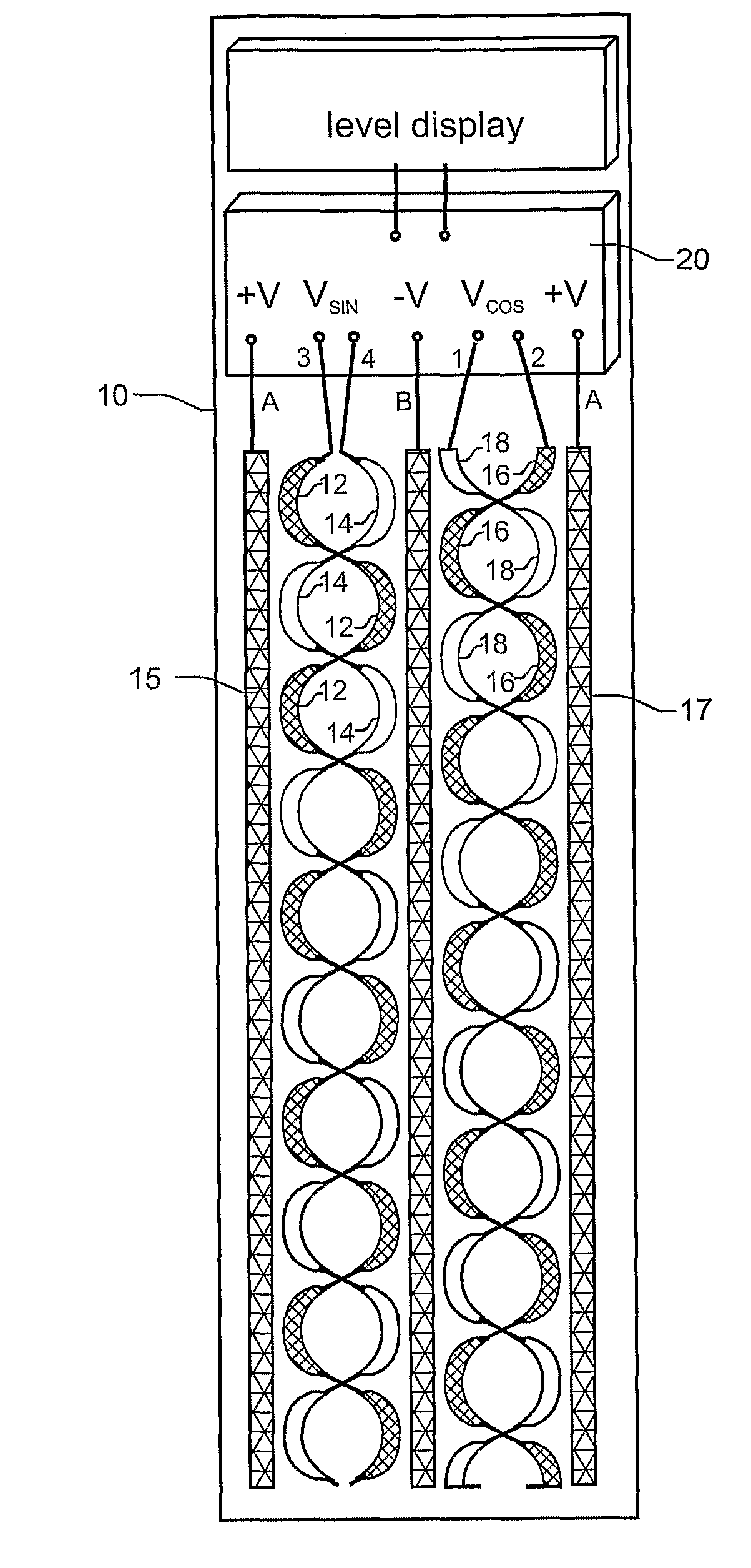
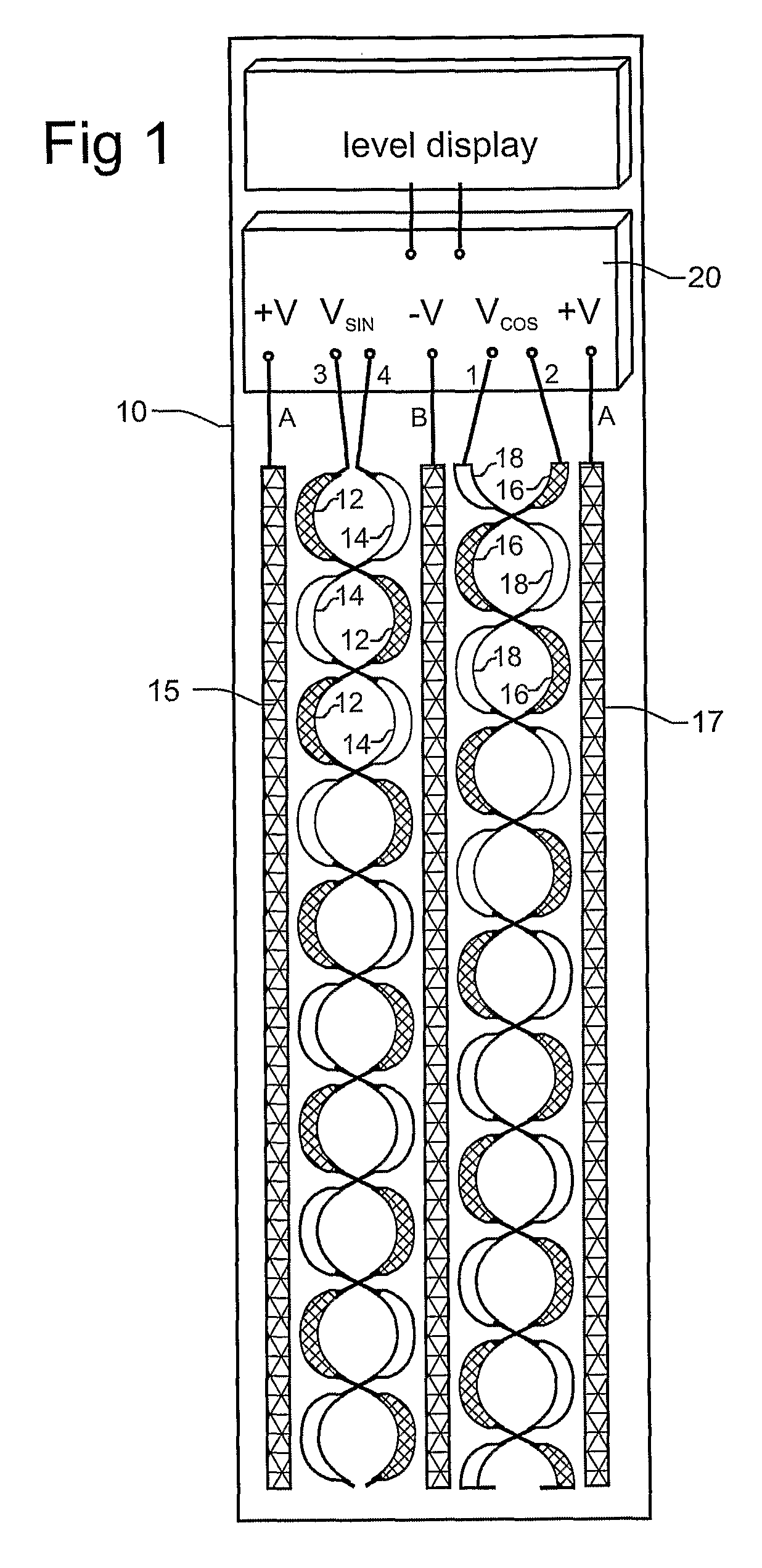
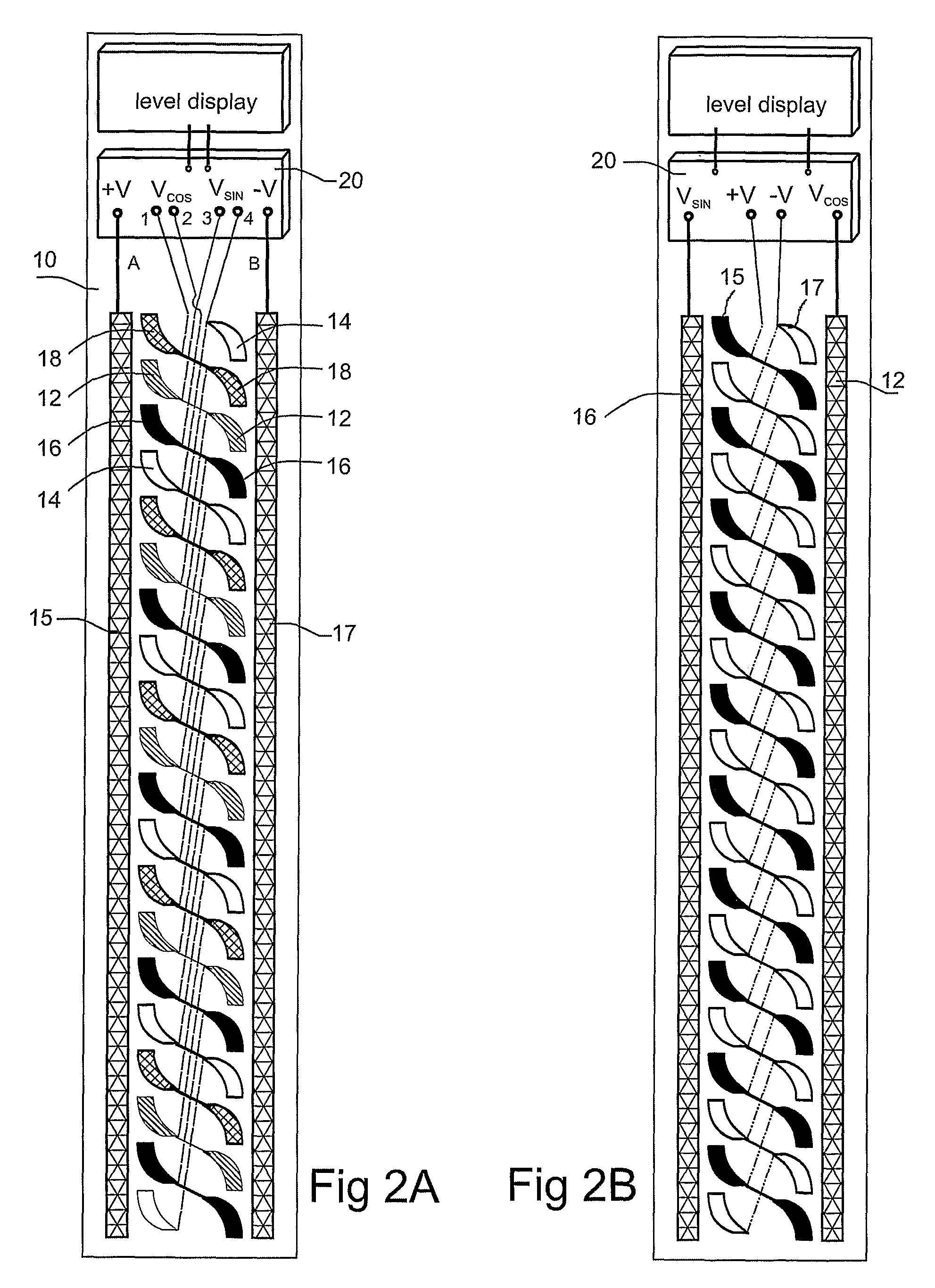
[0053]Embodiments of the invention enable detection of the spatial position of an inhomogeneity in the dielectric constant (permittivity) in the space around a sensor. The sensor may be arranged as an array of pixels along a straight line or any curved line. In general, this line is the measurement path. The sensor can detect the position of the interface between a liquid (or flowable materials like grain or powder) and the air, the position and displacement of a single dielectric or metallic object adjacent to the sensor, movement of an air bubble inside a liquid (e.g. in a level gauge), etc. The sensor may be placed externally near the dielectric (plastic or glass) walls or internally inside the container (e.g. in a fuel tank) but at the distance of at least a few centimetres from the metallic walls.

[0054]The measurement set-up of the sensor is based on detecting changes of the mutual capacitance between adjacent pixels in the array of pixels. This change is caused by the change o...


PUM


Abstract

A capacitive position sensor has a periodic array of electrodes which form capacitors between pairs of the electrodes. The location of a dielectric inhomogeneity in the vicinity of the sensor is determined by comparison of the relative change in the capacitance of the capacitors. The comparison may be carried out using a capacitive Wheatstone Bridge arrangement. The sensor configuration has the advantage that it is independent of the absolute value of the dielectric constant of the environment in which the sensor is located.

Description

FIELD OF THE INVENTION[0001]The present invention relates to a capacitive position sensor and in particular to a capacitive position sensor that is useful in determining a liquid level.BACKGROUND OF THE INVENTION[0002]Known capacitive liquid level sensors generally use two vertical spaced, for example coaxial, conductors to measure the change in capacitance between the conductors as the space between them fills with liquid. Such a sensor has the disadvantage that the capacitance of the conductors is not only dependent on the proportion of the space between them that is filled with liquid, but also to variations in the dielectric constant of the liquid. Consequently, if the composition of the liquid varies, which can be the case with automotive fuels for example, the liquid level sensor can become inaccurate.[0003]Capacitive proximity sensors are also known that respond to a change in the capacitance of the sensor due to the presence of a dielectric object in the vicinity of the sens...

Claims


Application Information

Patent Timeline
IPC IPC(8): G01R27/26G01F23/26
CPCG01F23/261G01F23/266G01F23/265
Inventor ZHITOMIRSKY, VICTOR EVGENIEVICH
Owner SCI GENERICS LTD
Why Eureka
Try Eureka